Eureka AIR delivers breakthrough ideas for toughest innovation challenges, trusted by R&D personnel around the world.

Semiconductor memory device having a plurality of chips and capability of outputting a busy signal

a memory device and semiconductor technology, applied in the field of semiconductor memory devices, can solve the problems of increasing the manufacturing cost of memory chips, the inability to control the memory chips from the outside, and the possibility of manufacturing defective memory cells high

Inactive Publication Date: 2006-01-24
KIOXIA CORP
View PDF10 Cites 7 Cited by
  • Summary
  • Abstract
  • Description
  • Claims
  • Application Information

AI Technical Summary

Benefits of technology

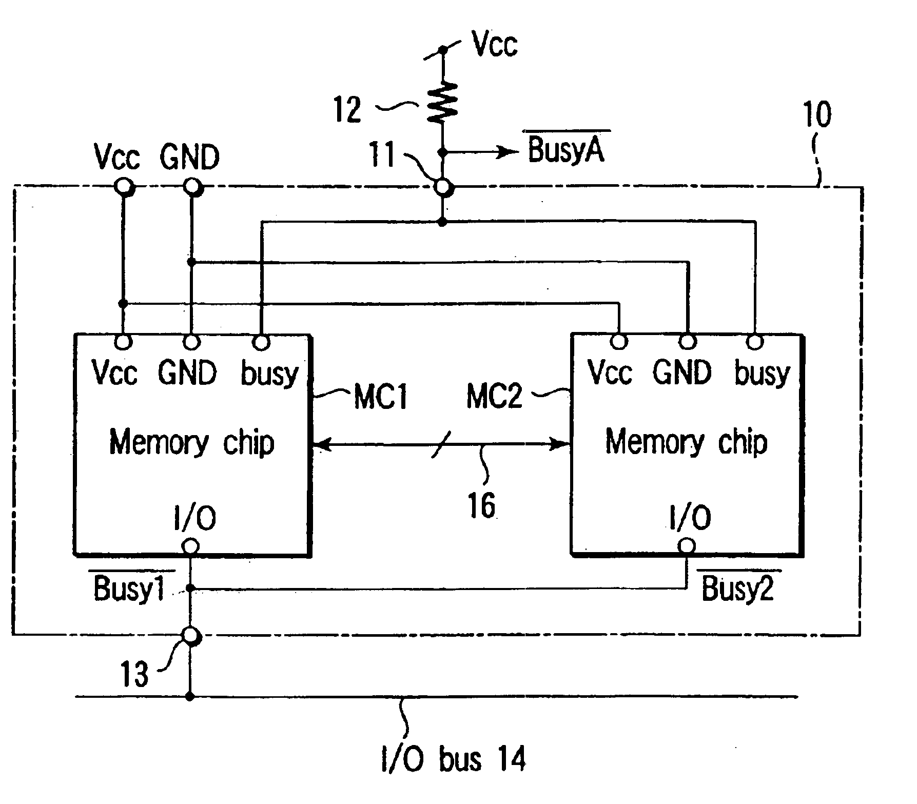
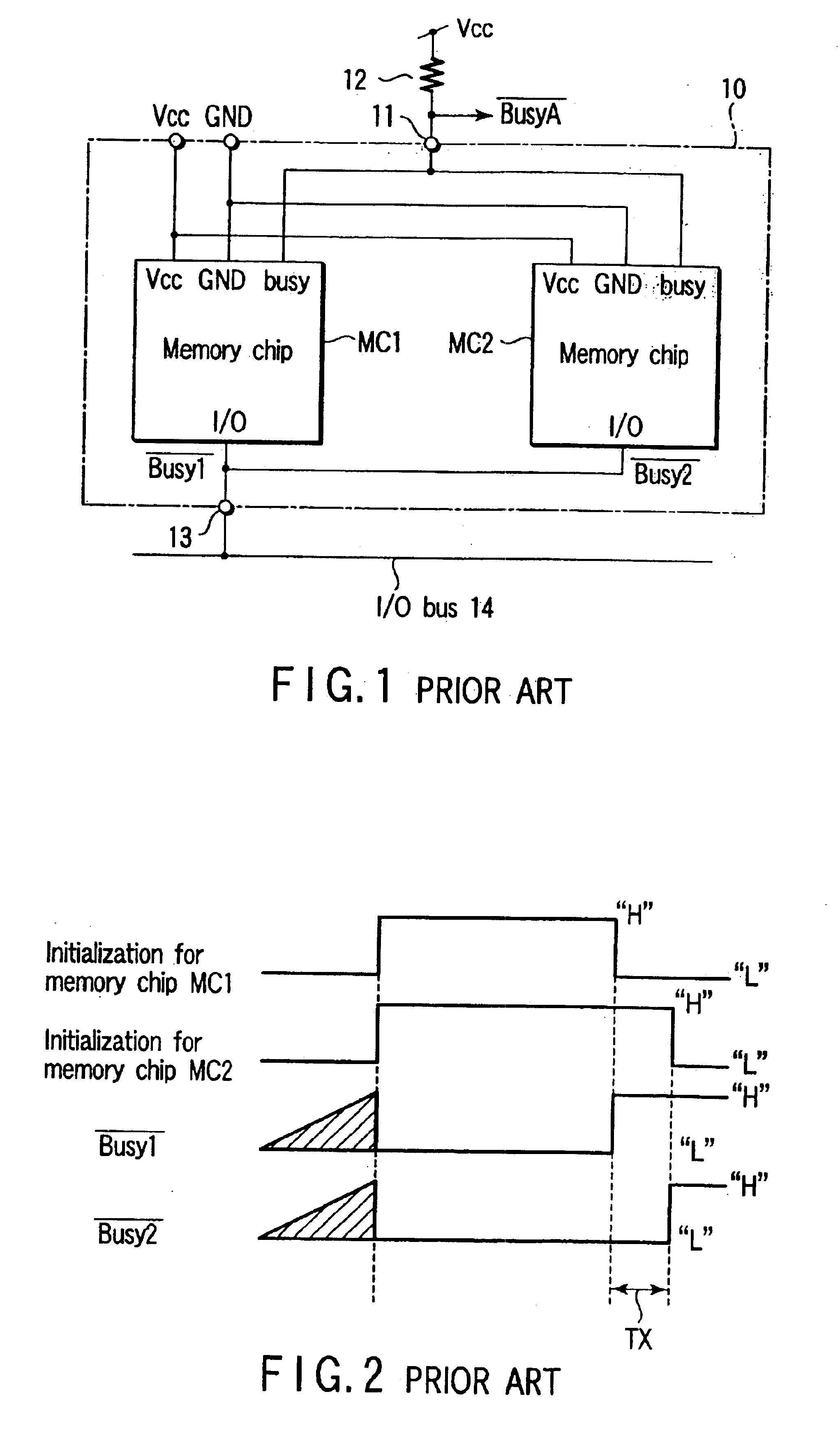
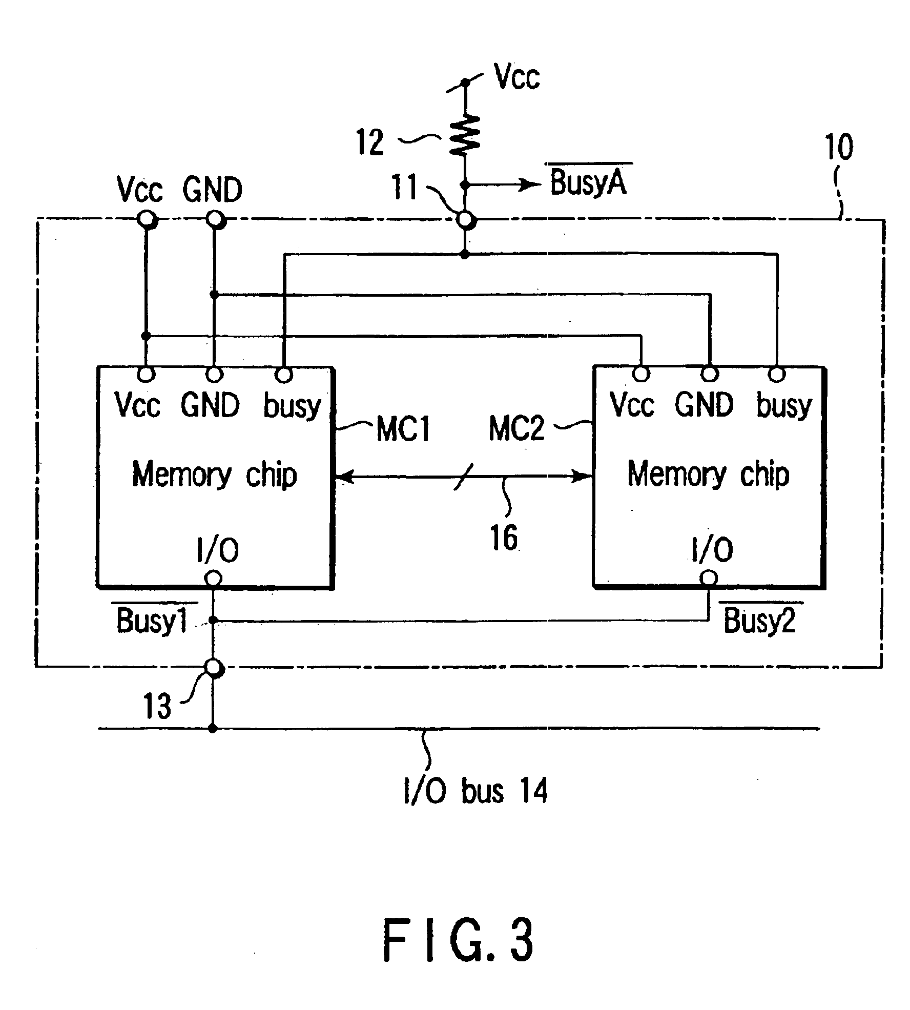
[0025]An aspect of the present invention, there is provided a semiconductor memory device including a plurality of memory chips in a package, wherein a busy state takes effect when the power supply voltage reaches a specified value after a power-on sequence; the busy state is maintained until completion of an initialization operation for the plurality of memory chips; and the busy state is released after completion of all initialization operations for the plurality of memory chips.

Problems solved by technology

There is a high possibility of manufacturing defective memory cells.
However, this method greatly increases manufacturing costs of memory chips.
During the initialization period, the memory chip cannot be controlled from the outside.
In this case, the system using the memory chip requires an extra operation of measuring the time, complicating the memory chip control.
This short circuit may cause the chip to malfunction due to the raised ground voltage level or lowered supply voltage level in each chip.
A large amount of current may flow between chips via the I / O bus 14, causing a possibility of destroying the device itself.

Method used


Image

  • Semiconductor memory device having a plurality of chips and capability of outputting a busy signal
  • Semiconductor memory device having a plurality of chips and capability of outputting a busy signal
  • Semiconductor memory device having a plurality of chips and capability of outputting a busy signal

Examples


first embodiment

[0091]FIG. 8 is a circuit diagram specifically showing a partial configuration of the busy control circuit 32 in FIG. 4 which is provided in each of the two memory chips MC1 and MC2 in the memory device according to the present invention. In this case, the above-mentioned method (2) is used.

[0092]The busy control circuit 32 has the same circuit configuration in both memory chips MC1 and MC2. The busy control circuits are represented by the reference numerals 32-1 and 32-2 in the memory chips MC1 and MC2, respectively.

[0093]At the power-on time, the memory chips MC1 and MC2 generate internal busy signals busy1 and busy2. Each of busy signals busy1 and busy2 is supplied to the gate of an N-channel MOS transistor 51 and one input terminal of a 2-input NOR circuit 52 in the busy control circuits 32-1 and 32-2. The source of the transistor 51 is connected to the ground voltage node. The drain is connected to the busy state output terminal 11 via the pad on the chip. As mentioned above, t...

second embodiment

[0115]FIG. 13 is a circuit diagram specifically showing a partial configuration of the busy control circuit 32 in the memory device according to the present invention. In this case, the above-mentioned method (1) is used.

[0116]The busy control circuit 32 has the same circuit configuration in both memory chips MC1 and MC2. The busy control circuits are represented by the reference numerals 32-1 and 32-2 in the memory chips MC1 and MC2, respectively. The busy control circuits 32-1 and 32-2 each are provided with the N-channel MOS transistor. 51, the output control circuit 53, and the 2-input AND circuit 54. The gate of the MOS transistor 51 is supplied with internal busy signals busy1 and busy2 generated in the memory chips MC1 and MC2. The source of the transistor 51 is connected to the ground voltage node. The drain is connected to the busy state. output terminal 11 via the busy state output pad on the chip. The terminal 11 is connected to the node of the power supply voltage Vcc vi...

third embodiment

[0121]FIG. 14 is a circuit diagram specifically showing a partial configuration of the busy control circuit 32 in the memory device according to the present invention. In this case, the above-mentioned method (2) is used.

[0122]The busy control circuit 32 has the same circuit configuration in both memory chips MC1 and MC2. The busy control circuits are represented by the reference numerals 32-1 and 32-2 in the memory chips MC1 and MC2, respectively.

[0123]The busy control circuits 32-1 and 32-2 each are provided with the N-channel MOS transistor 51, the output control circuit 53, the 2-input AND circuit 55, an N-channel MOS transistor 56, and a load resistor 57. The gate of the MOS transistor 51 is supplied with internal busy signals busy1 and busy2 generated in the memory chips MC1 and MC2. The source of the transistor 51 is connected to the ground voltage node. The drain is connected to the busy state output terminal 11 via the busy state output pad on the chip. The terminal 11 is c...


PUM


Abstract

One package contains a plurality of memory chips. Each memory chip has an I / O terminal which generates, a busy signal. The busy signal enables a busy state when a power supply voltage value reaches a specified and guaranteed range after a power-on sequence. The busy signal maintains the busy state until completion of initialization operations for the plurality of memory chips. The busy signal releases the busy state after completion of all initialization operations for the plurality of memory chips.

Description

CROSS-REFERENCE TO RELATED APPLICATIONS[0001]This application is a continuation of Ser. No. 10 / 185,645, filed Jun. 28, 2002, now U.S. Pat. No. 6,680,858 the entire contents of which are incorporated herein by reference.[0002]This application is based upon and claims the benefit of priority from the prior Japanese Patent Applications No. 2001-198132, filed Jun. 29, 2001; No. 2001-377408, filed Dec. 11, 2001; and No. 2002-159518, filed May 31, 2002, the entire contents of all of which are incorporated herein by reference.BACKGROUND OF THE INVENTION[0003]1. Field of the Invention[0004]The present invention relates to a semiconductor memory device such as an IC card, a memory system, etc. including a plurality of semiconductor memory chips in a package.[0005]2. Description of the Related Art[0006]As a semiconductor memory device, there is widely known an EEPROM (Electrically Erasable Programmable Read Only Memory) chip which enables rewriting of data. With respect to large integration, ...

Claims


Application Information

Patent Timeline
Patent Type & Authority Patents(United States)
IPC IPC(8): G11C5/06G11C7/10G11C7/20G11C16/20
CPCG11C5/143G11C7/1051G11C16/04G11C7/20G11C16/20G11C7/1063G11C7/1006G11C7/1072G11C7/1078G11C7/22
Inventor NAKAMURA, HIROSHIIMAMIYA, KENICHITAKEUCHI, KEN
Owner KIOXIA CORP
Why Eureka
Eureka Blog
Learn More