Method and apparatus to detect change in work tool

a technology of work tools and methods, applied in mechanical machines/dredgers, soil-shifting machines/dredgers, instruments, etc., can solve problems such as problems on the worksite, work machines are unable to perform their functions, and work machines are not attached

Inactive Publication Date: 2006-01-24
CATERPILLAR INC
View PDF6 Cites 101 Cited by
  • Summary
  • Abstract
  • Description
  • Claims
  • Application Information

AI Technical Summary

Problems solved by technology

Many work machines have work tools with engaging portions that wear or may come unattached in the course of performing their functions.
The engaging portions on work tools may wear or become detached from the work tool such that the work machine is unable to perform its function.
If the engaging portions become detached from the work tool other problems may occur on the worksite.
For example if bucket teeth from a wheel or track type loader become detached at a quarry site and an unattached tooth goes through a rock crusher, the rock crusher may be damaged and mining operations may cease for a time.
If wear or detachment occurs on the protrusions of the rotor on a planer or on the chisels on a soil tillage tool, the work these tools do may become uneven and may need to be repaired.
However, there are periods of time the operator may be unable to see the engaging portions of the work tool to ensure the engaging portions have not detached.
In other circumstances environmental factors such as dust may inhibit visibility.
On automated work sites where the work machine is automated or operated remotely, it may be impossible for an operator to visually inspect the work tool.
In some work environments this apparatus may fail.

Method used


Image

  • Method and apparatus to detect change in work tool
  • Method and apparatus to detect change in work tool
  • Method and apparatus to detect change in work tool

Examples


Embodiment Construction

[0017]While the invention is susceptible to various modifications and alternative forms, specific embodiments thereof have been shown by way of example in the drawings and will herein be described in detail. It should be understood, however, that there is no intent to limit the invention to the particular form disclosed, but on the contrary, the intention is to cover all modifications, equivalents, and alternatives falling within the spirit and scope of the invention as defined by the appended claims.

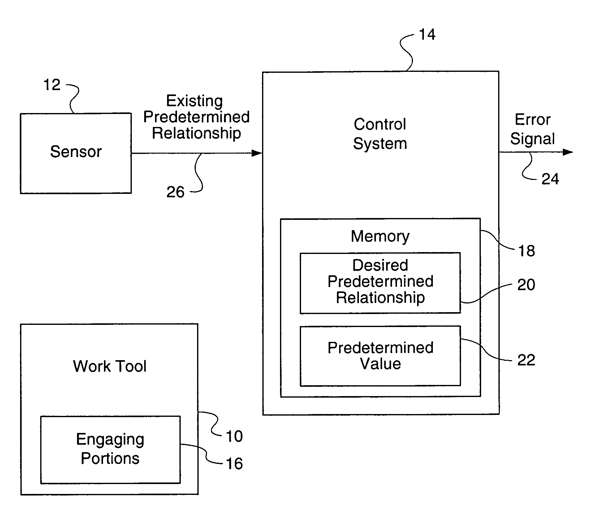
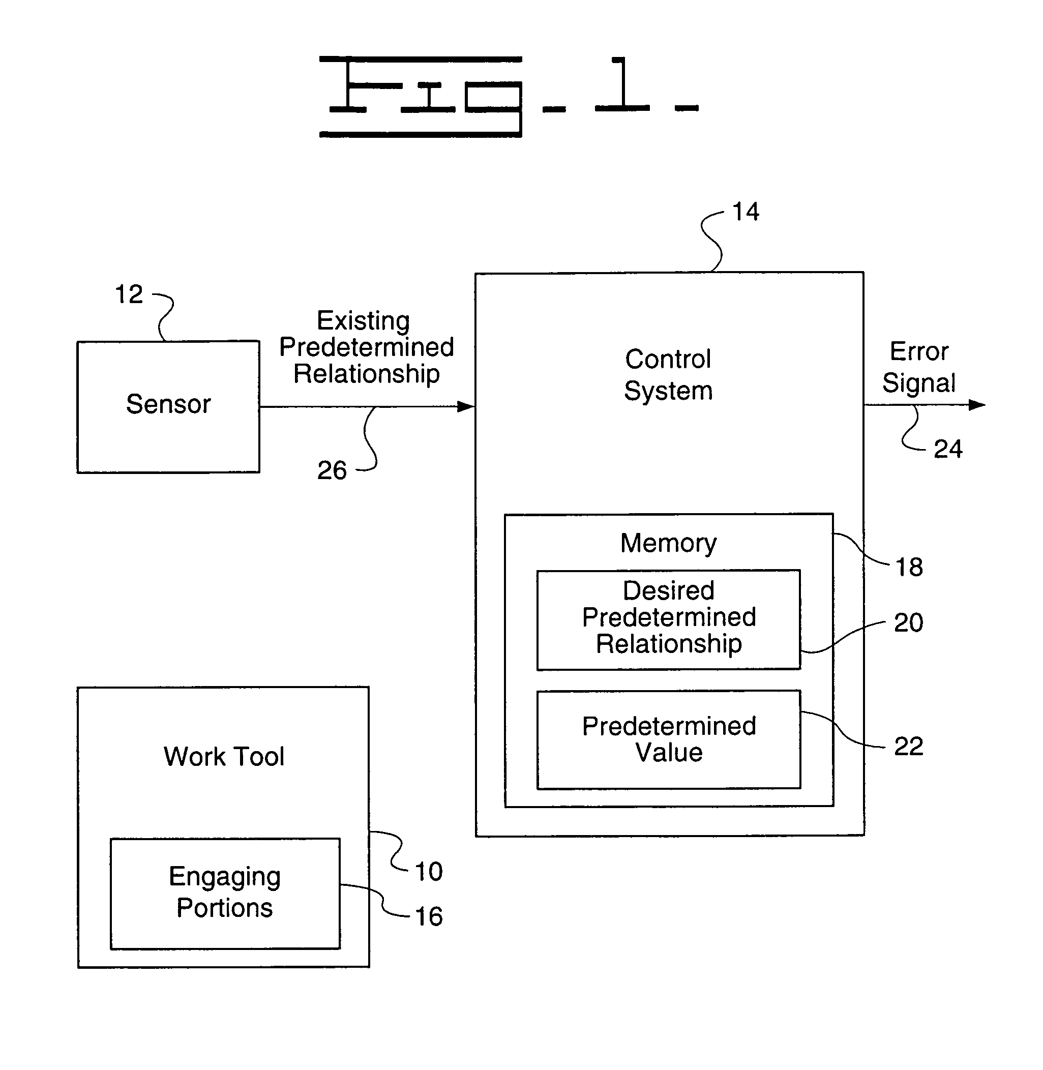
[0018]FIG. 1 shows a block diagram of an embodiment of the invention. It includes a work tool 10, a sensor 12 and a control system 14. The work tool 10, sensor 12 and control system 14 may be located on a work machine 302 (FIG. 3), 602 (FIG. 6). The work machine may be a wheel loader, a track-type tractor, an excavator, a cold planer, a track-type dozer, an agricultural machine with a tillage tool, a backhoe loader, a combine, a soil or landfill compactor or any other work machine that ...


PUM


Abstract

Method and apparatus to detect a change in a work tool with an engaging portion. A control system senses a change in the relationship between the engaging portion of the work tool and at least one of the work tool and another engaging portion of the work tool. If the change is greater than a predetermined value, the control system produces an error signal.

Description

TECHNICAL FIELD[0001]This invention relates generally to work machines and work machine implement controls and specifically to a method and apparatus to detect a change in a work tool.BACKGROUND[0002]Many work machines have work tools with engaging portions that wear or may come unattached in the course of performing their functions. For example, an excavator or a wheel or track type loader may have a bucket with attachable teeth. The teeth may be used to break up dirt or other material when the excavator or loader is digging. In another example, a cold planer may have a rotor with attachable teeth used to break up pavement. In still other examples a landfill or soil compactor may have protrusions on the wheels used to compact trash, an earthmoving machine such as a dozer or backhoe loader may have a ripper with ripper teeth or an agricultural tractor may pull a tillage tool with chisels or other protrusions or attachments.[0003]The engaging portions on work tools may wear or become...

Claims


Application Information

Patent Timeline
Patent Type & Authority Patents(United States)
IPC IPC(8): G06F19/00E02F3/43
CPCE02F3/435
Inventor GROTH, RONALD O.KEMNER, CARL A.LAY, N. KEITH
Owner CATERPILLAR INC
Why Eureka
Try Eureka