
Optical disc loading using two detecting arms and an edge sensor

a technology of edge sensor and optical disc, which is applied in the field of can solve the problems of foreign bodies being jammed into the device, the drive's sensor may not detect its presence, and the conventional slot-in optical disc drives have disadvantageous characteristics, etc., and achieve the effect of accurately determining the size of the optical disc inserted

Inactive Publication Date: 2006-01-24
LITE ON IT
View PDF6 Cites 23 Cited by
  • Summary
  • Abstract
  • Description
  • Claims
  • Application Information

AI Technical Summary

Benefits of technology

[0009]It is therefore an object of the present invention to provide a disc loading device for an optical disc drive that accurately determines the size of an optical disc inserted into the drive.
[0016]The apparatus and method of the present invention may be implemented at low cost. Furthermore, the apparatus and method of the present invention can accurately discriminate between standard sized optical discs and other objects.

Problems solved by technology

Conventional slot-in optical disc drives have disadvantageous characteristics.
For example, if a thin foreign body, such as an ID card, credit card, or phone card, is mistakenly inserted into the slot instead of an optical disc, the drive's sensor may fail to detect its presence.
Subsequently, the foreign body may be jammed into the device and damage the disc drive when another optical disc or object is inserted.
However, if many opposed-mode sensors are used to discriminate between optical discs and other objects, the structure of the drive becomes complex and costly.
On the other hand, if only a few opposed-mode sensors are disposed in the disc drive, the discrimination between optical discs and other objects cannot be performed accurately.
In addition, it is possible for a user to insert an optical disc or other object into the disc drive at an angle, which also can result in inaccurate discrimination.

Method used


Image

  • Optical disc loading using two detecting arms and an edge sensor
  • Optical disc loading using two detecting arms and an edge sensor
  • Optical disc loading using two detecting arms and an edge sensor

Examples


Embodiment Construction

[0027]For purpose of the present invention, the term “optical disc drive” or “disc drive” as used herein, shall include CD-ROM, CD-RW, DVD-R / RW, and DVD+RW drives, combo drives, external drives, and slim-type drives, as well as all other optical media recorders and players.

[0028]The following is a detailed description of preferred embodiments of the present invention. The description is not to be taken in a limiting sense, but is made merely for the purpose of illustration.

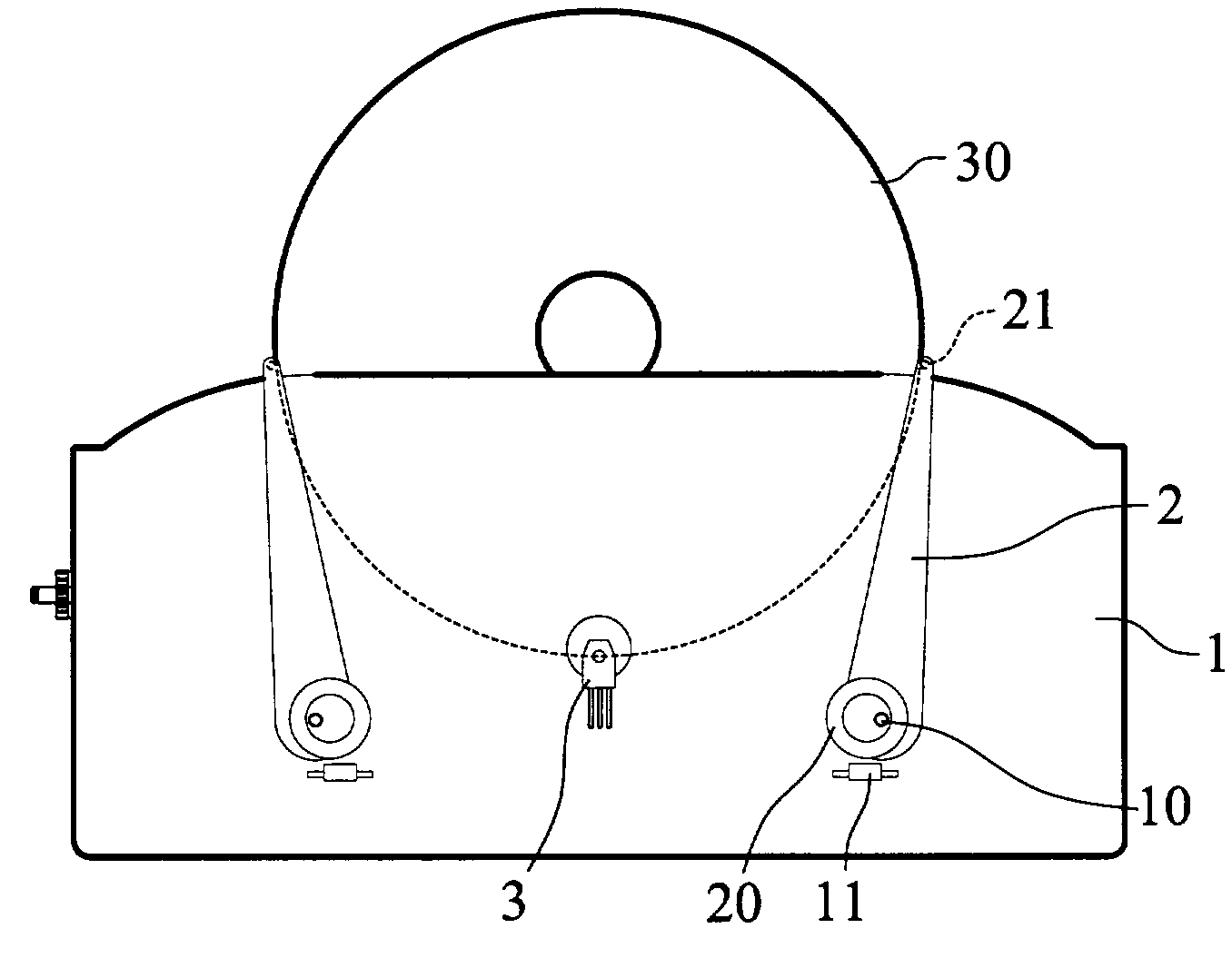
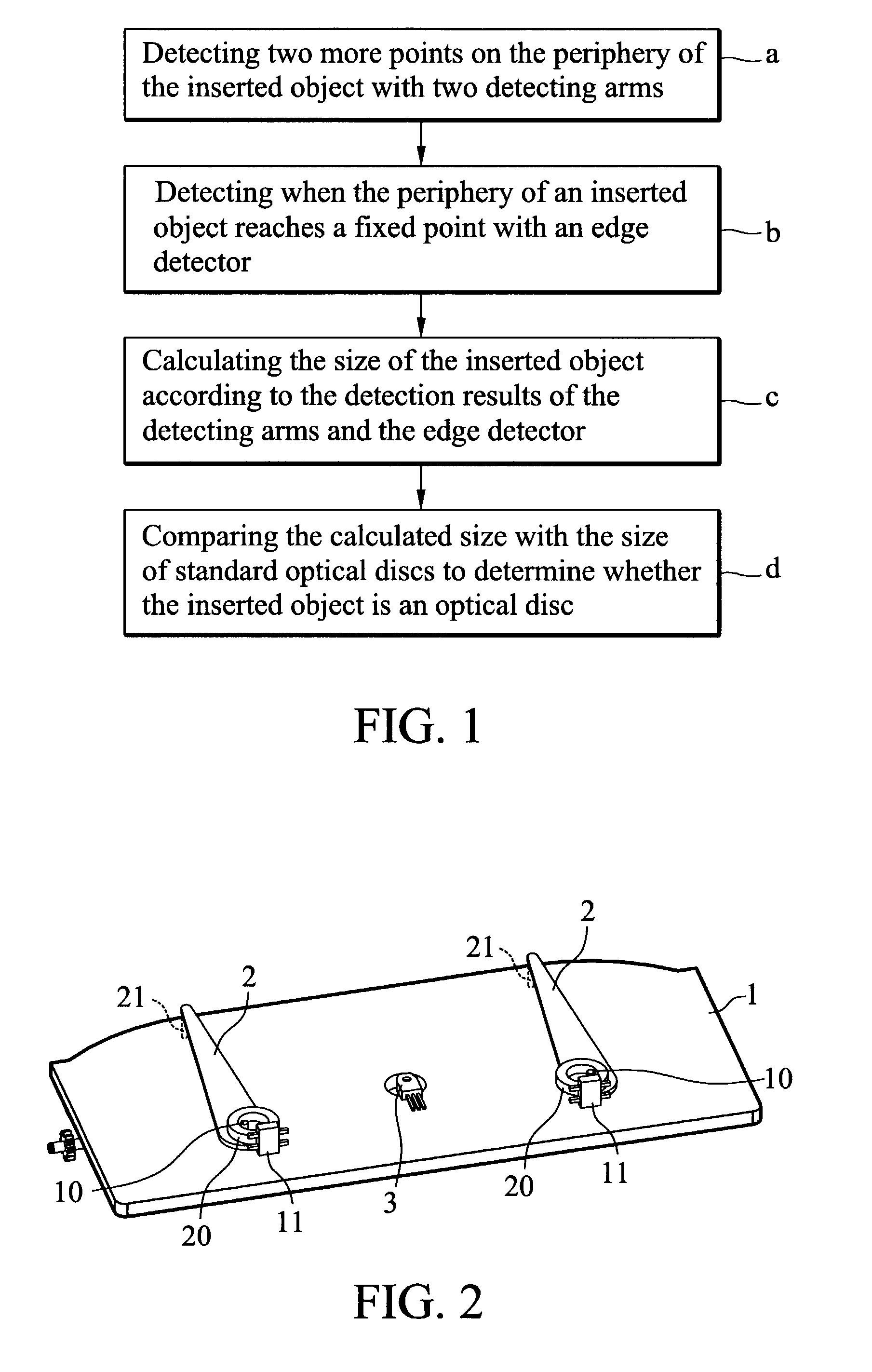
[0029]The present invention provides a disc loading device for an optical disc drive. FIG. 2 schematically shows a perspective view of the disc loading device of the optical disc drive according to an embodiment of the present invention.

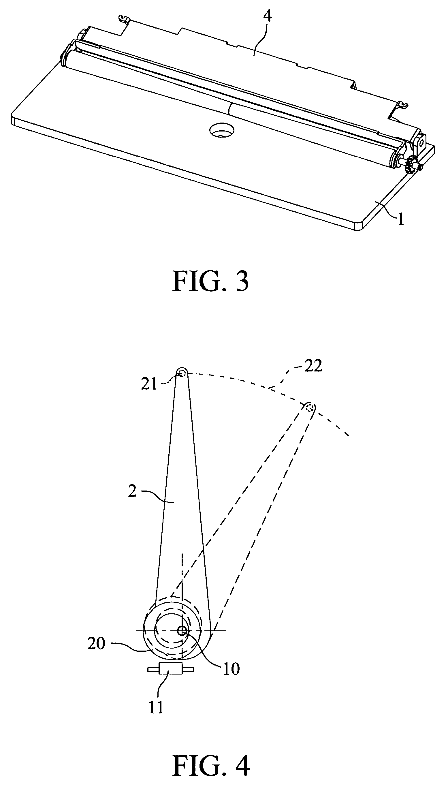
[0030]As shown in FIG. 2, the chassis 1 is used to support the components of the optical disc drive. In accordance with the present invention, the disc loading device has two detecting arms 2, an edge sensor 3, a control unit (not shown), and a roller assembly 4 which loads and unl...


PUM

PropertyMeasurementUnit
diameteraaaaaaaaaa
diameteraaaaaaaaaa
radiusaaaaaaaaaa

Abstract

A disc loading device for an optical disc drive that discriminates between standard sized optical discs and other objects. In the disc-loading device, two one-degree-of-freedom detecting arms are disposed near the slot of the optical disc drive. An edge sensor including an emitting component and a receiving component is disposed between two detecting arms. A control unit receives data from the detecting arms and the edge sensor when the edge sensor detects the periphery of an object inserted into the optical disc drive. The data is used to calculate the size of the inserted object. By comparing the measured size with the standard sizes of optical discs, the disc loading device can determine whether or not the inserted object is an optical disc or another object. If the control unit determines that the inserted object is not an optical disc, the object is unloaded.

Description

BACKGROUND OF THE INVENTION[0001]1. Field of the Invention[0002]The present invention relates to a slot-in disc drive, and in particular to a disc loading device for use in a slot-in optical disc drive for receiving optical discs of different sizes while unloading other objects inserted into the drive.[0003]2. Description of the Prior Art[0004]Slot-in optical disc drives allow users to conveniently load and unload optical discs. Slot-in optical disc drives can be implemented in various electronic devices, for example notebook computers and car CD players. As for the operation of these disc drives, rollers or other means are used to apply force to the circular periphery of the optical disc, thereby loading or unloading optical discs.[0005]Conventional slot-in optical disc drives have disadvantageous characteristics. For example, if a thin foreign body, such as an ID card, credit card, or phone card, is mistakenly inserted into the slot instead of an optical disc, the drive's sensor m...

Claims


Application Information

Patent Timeline
Patent Type & Authority Patents(United States)
IPC IPC(8): G11B17/04
CPCG11B17/051G11B17/0404
Inventor LEE, CHENG-FU
Owner LITE ON IT
Features
  • Generate Ideas
  • Intellectual Property
  • Life Sciences
  • Materials
  • Tech Scout
  • Unparalleled Data Quality
  • Higher Quality Content
  • 60% Fewer Hallucinations
Learn More