Fuel rail delivery system arrangement

a technology of fuel rail and delivery system, which is applied in the direction of liquid fuel feeders, combustion air/fuel air treatment, machines/engines, etc., can solve the problem of increasing the overall size of fuel rails, and achieve the effect of minimizing the chance of damage to the fuel injector and easy installation

Inactive Publication Date: 2006-01-31
MILLENNIUM INDS
View PDF5 Cites 13 Cited by
  • Summary
  • Abstract
  • Description
  • Claims
  • Application Information

AI Technical Summary

Benefits of technology

[0008]The present invention is advantageous in that it allows the fuel rails to be placed generally vertically aligned with each other and also allows their placement at a central point of the engine when utilizing V-type engines. Additionally, the inventive fuel air delivery system arrangement allows for easier installation of the fuel injectors between the fuel rails and the fuel injector inlets and also allows for placement of the fuel injectors in such a manner that minimizes opportunities for damaging the fuel injector due to misalignment during assembly.

Problems solved by technology

This tendency of utilizing the fuel rail itself to dampen pulsations has caused the overall size of fuel rails to generally increase.

Method used


Image

  • Fuel rail delivery system arrangement
  • Fuel rail delivery system arrangement
  • Fuel rail delivery system arrangement

Examples


Embodiment Construction

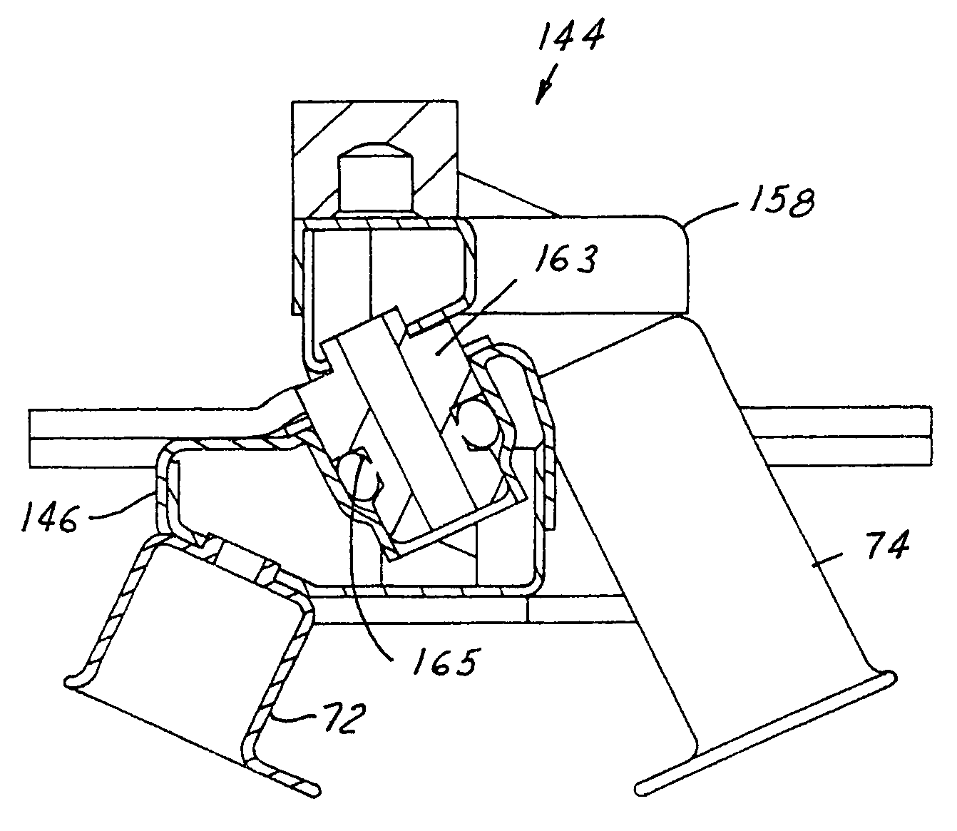
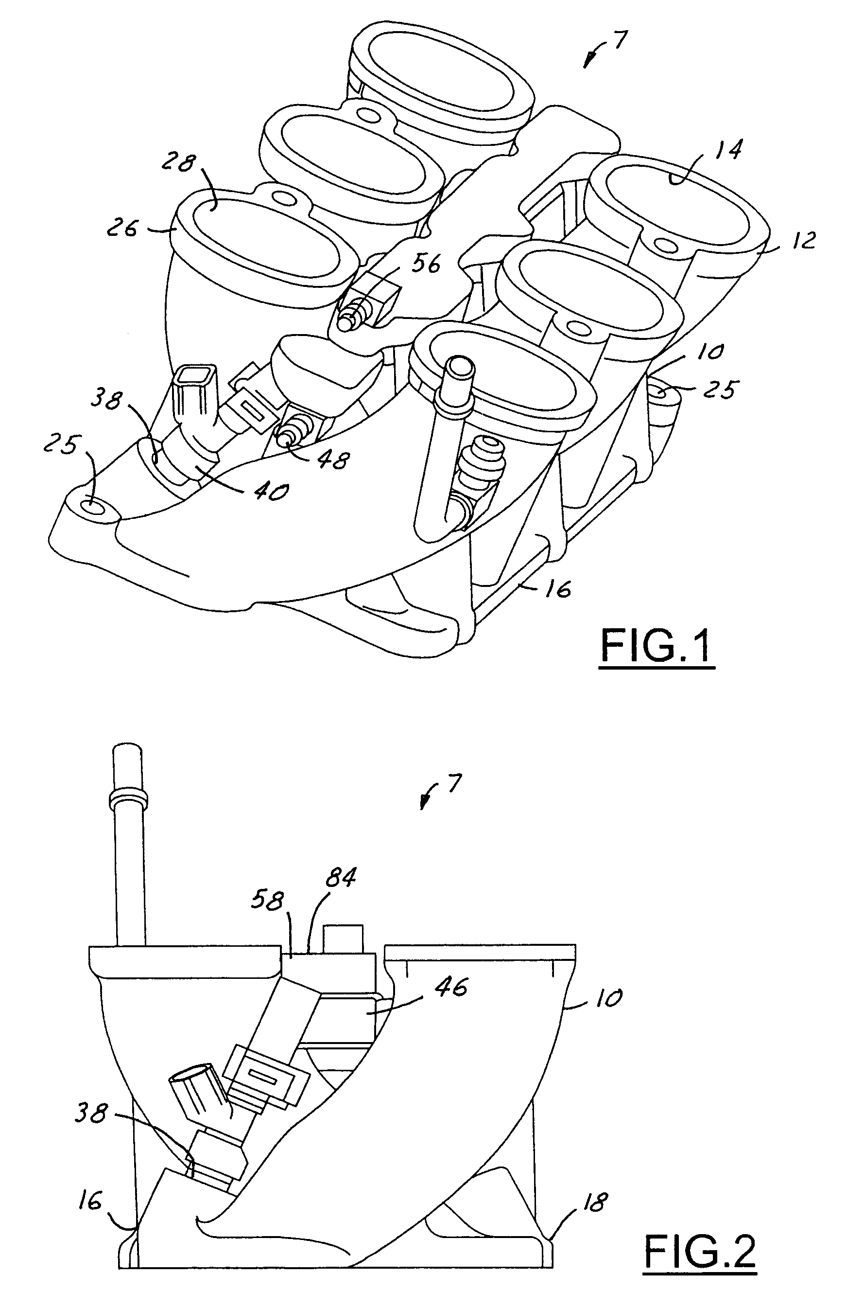
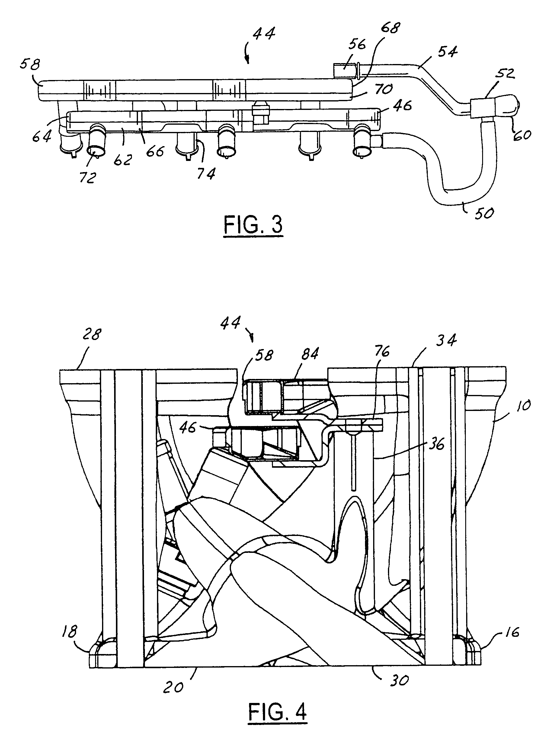
[0018]Referring to FIGS. 1–4, an air fuel delivery system arrangement 7 is provided. This air fuel delivery system arrangement is preferably used in a V-type reciprocating piston, spark-ignited, internal combustion engine. The air fuel delivery system arrangement 7 is particularly useful in V-type engines wherein the combustion cylinders are inclined from one another 60 degrees or less, which typically has most applications in automotive engines that are transverse mounted in front wheel drive vehicles.

[0019]The arrangement 7 includes an air manifold body 10. The air manifold body 10 is typically a molded thermoplastic polymeric material such as Nylon®, plastic or can be aluminum or other suitable material. Often, the material will be fiberglass reinforced. The manifold body has a first set of runners 12. The runners 12 have air inlets 14 on a first side 16 of the air manifold body. The air manifold body 10, on its second side 18, has a series of air outlets 20 for the runners 12. T...


PUM


Abstract

An air fuel delivery system arrangement for an engine is provided, including an air manifold body, having a first set of runners for a first cylinder bank with inlets on a first side and outlets on a second side of the manifold body and a second set of runners for a second cylinder bank with inlets on a second side and outlets on a first side. And a first fuel rail is included, having outlets for connection with fuel injectors for delivering fuel to the first cylinder bank being positioned generally between the inlets of the manifold body. A second fuel rail is also included, having outlets for connection with fuel injectors for delivering fuel to the second cylinder bank being positioned generally between the inlets of the manifold body being generally vertically aligned with the first fuel rail.

Description

FIELD OF THE INVENTION[0001]The field of the present invention is air and fuel delivery system arrangements for reciprocating piston, internal combustion engines. The present invention relates particularly to V-type internal combustion engines having spark-ignited, multiple injector fuel systems.BACKGROUND OF THE INVENTION[0002]In order to increase fuel economy, there has been a constant quest to reduce the physical envelope of the vehicle engine so that the engine compartment may be made smaller to accomplish aerodynamic improvements in the overall vehicle. Additionally, another trend to improve vehicle fuel economy is to go to fuel injection systems wherein each engine cylinder receives fuel from an individualized fuel injector.[0003]Most V-type automotive engines utilize two separate fuel manifolds (more commonly referred to as fuel rails), which deliver fuel pressurized by a fuel pump to a group or bank of fuel injectors. In most applications, the fuel rails are connected to bra...

Claims


Application Information

Patent Timeline
Patent Type & Authority Patents(United States)
IPC IPC(8): F02M37/04
CPCF02M69/462F02M69/465F02M2200/40F02M2200/315
Inventor ZDROIK, MICHAEL J.DOHERTY, ROBERTROE, JACKSON ZEL
Owner MILLENNIUM INDS
Why Eureka
Try Eureka