Gas friction pump

a friction pump and gas technology, applied in the direction of shafts, liquid fuel engines, motors, etc., can solve the problems of difficult oil supply, high replacement cost, limited service life of ball bearings, etc., and achieve high rotation speed, high stiffness, and better absorb high reaction forces

Inactive Publication Date: 2006-01-31
PFEIFFER VACUUM GMBH
View PDF5 Cites 0 Cited by
  • Summary
  • Abstract
  • Description
  • Claims
  • Application Information

AI Technical Summary

Benefits of technology

[0016]In a gas friction pump with a bell-shaped or floating rotor, the bearing, which is located closer to the gravity center, is capable to better absorb high reaction forces when a gas bearing is used in this location. Gas bearings have a high stiffness and operate at necessary high rotation speeds. They are subjected only to a minimal wear, thereby increasing the maintenance intervals and, as a result, significantly reducing costs.
[0017]By using only one gas radial beari

Problems solved by technology

Despite this, the service life of a ball bearing is limited, and a replacement should take place in regular intervals.
Therefore, the oil supply is difficult and the replacement expensive.
A further problem is created by hydrocarbon vapors which are released from the oil of the bearing.
This is highly undesirable during the manufacturing of semiconductors.
In comparison with ball bearings, noticeably higher technical expenses lead to high manufactu

Method used


Image

  • Gas friction pump
  • Gas friction pump

Examples


Embodiment Construction

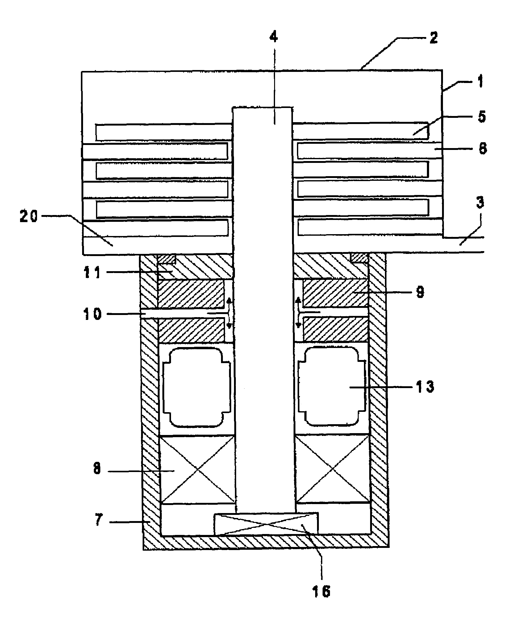
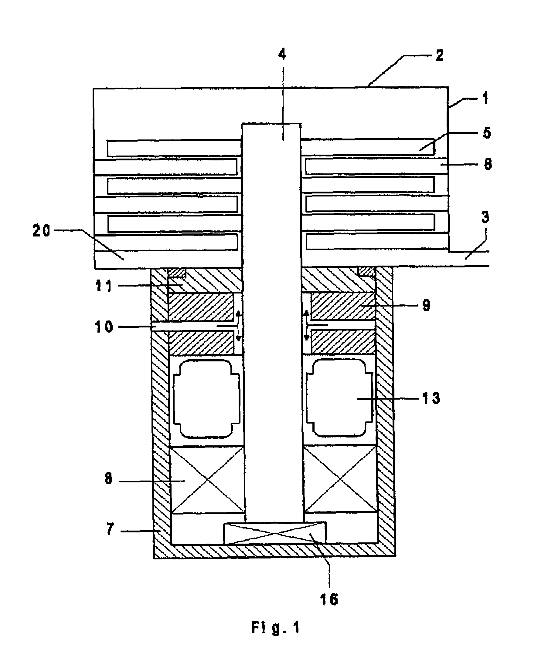
[0019]Based on a single drawing, the present invention will be explained and further advantageous embodiments will be discussed. The drawing shows an embodiment of a turbomolecular pump with a floating rotor. In a pump housing 1 with a suction flange 2 and an outlet opening 3, there are mounted stationary pump-active components such as stator discs 6. Rotatable pump-active components are formed by rotor discs 5 fixedly mounted on a rotor shaft 4. A drive 13 provides for its rotation.

[0020]For supporting the rotor shaft, in a cylindrical housing part 7, adjacent to the drive, there are located lower bearing unit 8 and upper bearing unit 9. A bearing 16 supports the rotor shaft axially. In the shown embodiment, the axial bearing, which is located at the lower end of the rotor shaft, can be placed at another location, e.g., in vicinity of the upper radial bearing 9. Sealing means 11 is provided between the upper bearing unit and a gas outlet region 20. The upper bearing unit is formed ...


PUM


Abstract

A gas friction pump includes stationary (6) and rotatable (5) pump-active elements secured on a rotor shaft (4) and forming with the rotor shaft components of the rotor, with the rotor shaft (4) being supported by two, spaced from each other, radial bearings (8, 9), of which one is located closer to the gravity center of the rotor than the other, and an axial bearing (16), and with the radial bearing (9), which is located closer to the gravity center of the rotor, being formed as a gas bearing, and another radial bearing (8) being formed as a non-gas bearing.

Description

BACKGROUND OF THE INVENTION[0001]1. Field of the Invention[0002]The present invention relates to a gas friction pump including stationary pump-active elements and rotatable pump-active elements cooperating with the stationary pump-active elements. The rotatable pump-active elements are secured on a rotatable rotor shaft. The rotor shaft and the rotatable pump-active elements form components of the rotor. The rotor shaft is supported by two, spaced from each other, radial bearings of which one is located closer to the center of gravity of the rotor, and by an axial bearing.[0003]2. Description of the Prior Art[0004]Gas friction pumps, in particular, turbomolecular pumps are successfully used in many applications where a low end vacuum needs to be reached.[0005]The term turbomolecular pump follows from the similarity with turbines, i.e., with blade rings being alternative supported on rotor and stator. The pumping effect is produced by cooperation of the rotor and the stator and incre...

Claims


Application Information

Patent Timeline
IPC IPC(8): F04D29/04F04D29/056F04D19/04F04D29/057F04D29/059
CPCF04D19/04F04D29/059F04D29/057F16C2360/45
Inventor CONRAD, ARMINSTANZEL, JORG
Owner PFEIFFER VACUUM GMBH
Why Eureka
Try Eureka