Hand manipulated tool

a technology of manipulating tools and tools, which is applied in the direction of gear teeth, gear cleaning devices, gear teeth, etc., can solve the problems of uneven sanding, uneven sanding, and damage to the surface of the wall

Inactive Publication Date: 2006-01-31
FULL CIRCLE INT
View PDF38 Cites 32 Cited by
  • Summary
  • Abstract
  • Description
  • Claims
  • Application Information

AI Technical Summary

Problems solved by technology

However, when the device is manipulated, due to its narrow configuration, the device tends to flip onto its elongate sides and can damage the surface of the wall, for example by gouging the surface with the corners or edges of the device, requiring filling or additional sanding to remove the damage.
However, since the isosceles triangle has a tall narrow profile, this device also has a narrow region near the attachment to the handle and encounters the same flipping problem.
Additionally, the angles do not match that of most corners on surfaces and therefore, a corner of the device needs to be moved around the area of the corner of the surface in order to completely work such an area.
This approach can lead to uneven sanding and increases the risk of poking the corner of the device into one of the adjacent walls forming the corner.
These devices are larger and more cumbersome due to the mechanical motor assembly and have a circular, non-continuous “O” shaped working surface due to the need to have access to a bolt.
This device takes a greater level of skill to master and if used improperly, can damage the surface by dishing to create swirl marks in the surface.

Method used


Image

  • Hand manipulated tool
  • Hand manipulated tool
  • Hand manipulated tool

Examples


Embodiment Construction

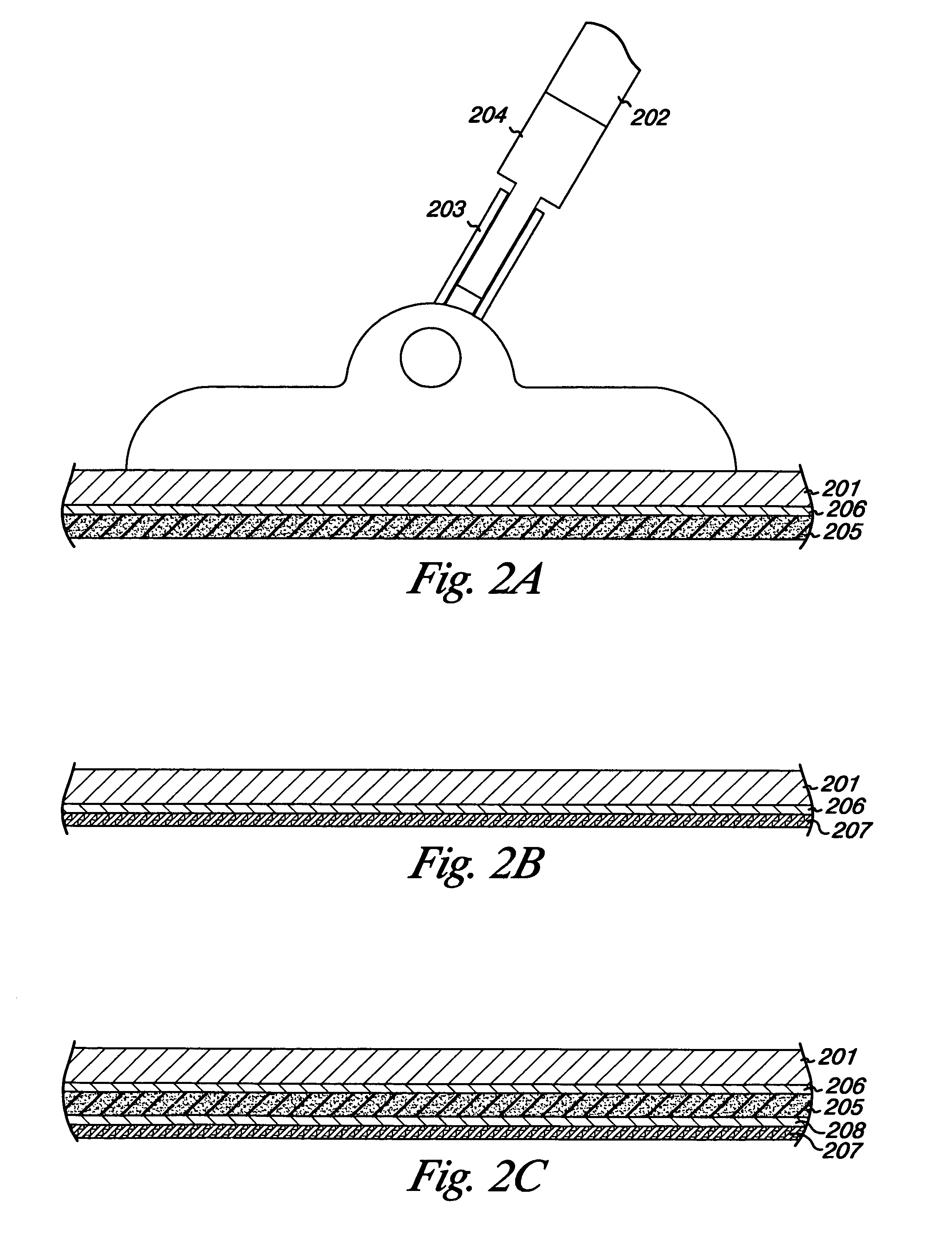
[0016]Embodiments of the present invention provide working devices that reduce the potential for tipping of a head of the device on its side.

[0017]As one of ordinary skill in the art will appreciate upon reading this disclosure, a working device can be utilized in many fields depending upon what working material is utilized.

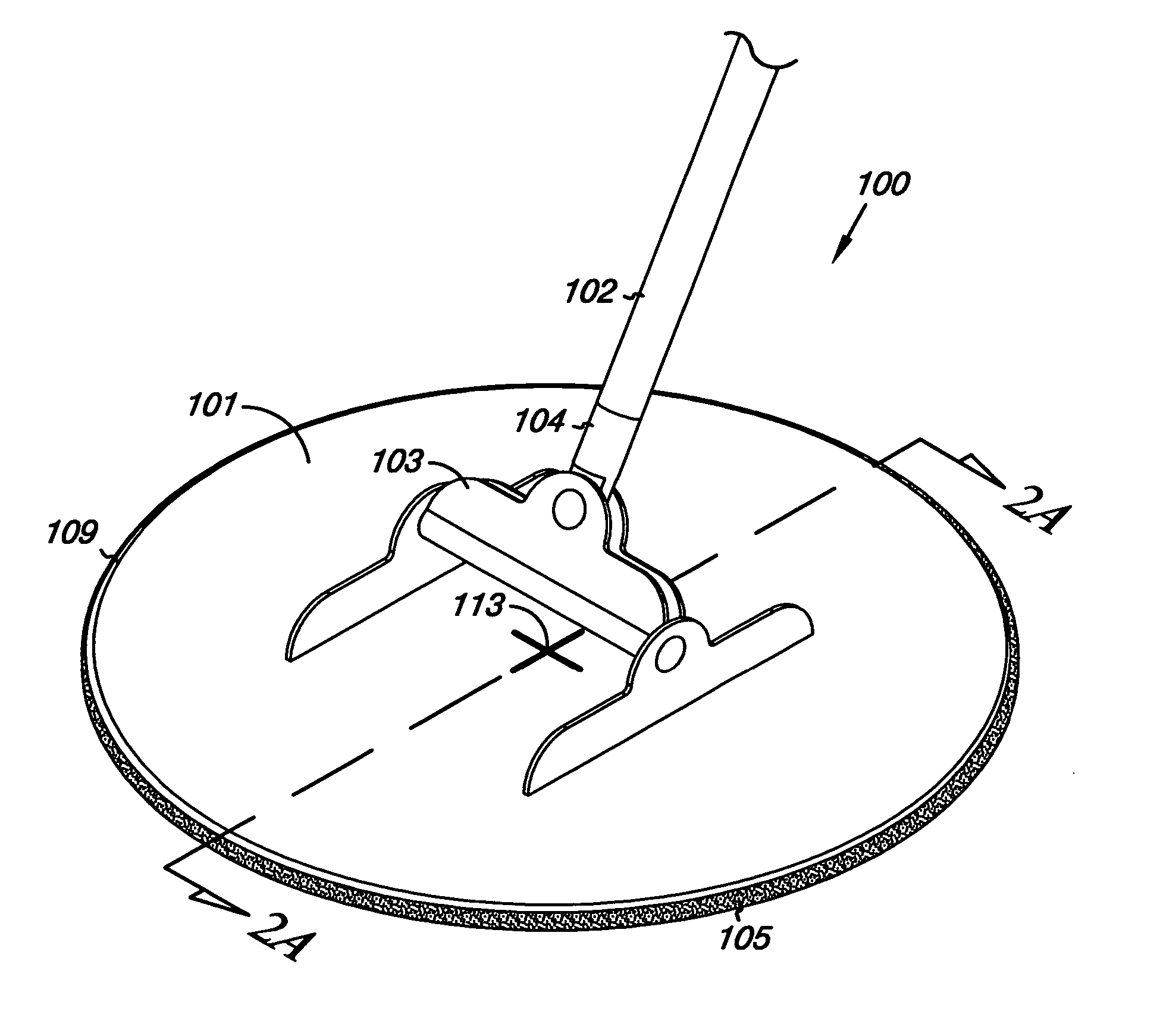
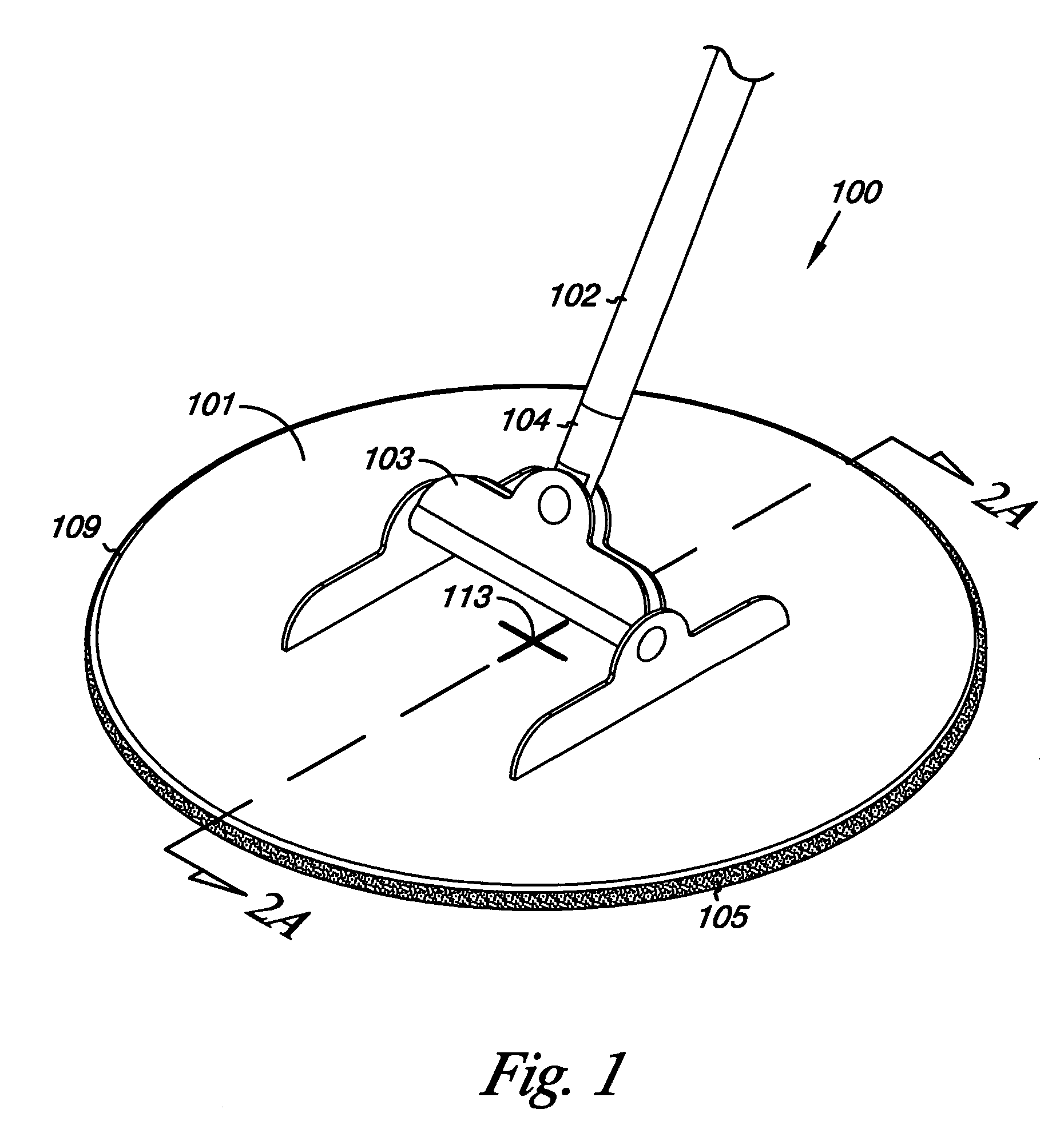
[0018]FIG. 1 illustrates a top perspective view of an embodiment of a device head 100 attached to a handle 102. In this embodiment, the handle 102 is an elongate handle, such as a broom handle, dowel, or extended pole, however, the invention is not so limited.

[0019]In FIG. 1, the device head 100 includes a tool support 101 that can be attached to the handle 102 in any manner. For example, as shown in FIG. 1, the tool support 101 can be attached to the handle 102 by a pivoting structure. In the example shown, a two piece, two directional structure is provided. In this example, a first piece 103 having a first pivoting point is connected to a second piece 104 also ...


PUM

PropertyMeasurementUnit
angleaaaaaaaaaa
sizeaaaaaaaaaa
resilientaaaaaaaaaa

Abstract

An embodiment of a hand manipulated tool includes an elongate handle and a tool support. The tool support has a center, rotationally fixed to the elongate handle. The tool support has a periphery with at least five points equidistant from the center.

Description

INTRODUCTION[0001]Hand held tools have been utilized in many fields for working the surface of a material, such as sanding, polishing, and painting, among others. For example, when fabricating a structure, such as a wall or ceiling in a building, oftentimes it is necessary to utilize a sanding device to smooth the surface of the structure. In response to this need, in the field of sanding devices for example, devices have been proposed.[0002]One device utilizes a sanding head having an elongate rectangular head. This head is designed to accommodate a standard sized elongate sheet of sand paper, thereby making the supply of sanding paper readily accessible. However, when the device is manipulated, due to its narrow configuration, the device tends to flip onto its elongate sides and can damage the surface of the wall, for example by gouging the surface with the corners or edges of the device, requiring filling or additional sanding to remove the damage.[0003]A device has also been pro...

Claims


Application Information

Patent Timeline
Patent Type & Authority Patents(United States)
IPC IPC(8): B23F21/03A47L13/24A47L13/29B24B7/18B24D15/00
CPCA47L13/24B24D15/00B24B7/184A47L13/29
Inventor ANNIS, KENT V.HARLOW, KARL W.
Owner FULL CIRCLE INT
Why Eureka
Try Eureka