Control of powertrain smoothness using output torque sensing and input torque control

a technology of output torque and input torque, which is applied in the direction of mechanical equipment, driver input parameters, transportation and packaging, etc., can solve the problems of noise, vibration and harshness, and the quality of gear shifts produced by automatic transmissions operating under electronic control that employ conventional control strategies often lacks the desired smoothness, and achieves simplified hydraulic controls. , the effect of avoiding costly one-way clutches, coast clutches and extra controls

Active Publication Date: 2006-01-31
FORD GLOBAL TECH LLC
View PDF10 Cites 49 Cited by
  • Summary
  • Abstract
  • Description
  • Claims
  • Application Information

AI Technical Summary

Benefits of technology

[0007]The powertrain control strategy according to the present invention avoids unwanted output torque disturbance when the control is not performing a gear shift, during the torque phase of the shift, and during the inertia phase of the shift. This invention is applicable to all-synchronous shifting, uses simplified hydraulic controls, and avoids costly one-way clutches, coast clutches and extra controls that are normally required for each non-synchronous gear ratio change.

Problems solved by technology

Because shift quality control in automatic transmissions for motor vehicles is attempted using incomplete information from power train sensors, the quality of gear shifts, often called shift feel, produced by automatic transmissions operating under electronic control that employ conventional control strategies often lacks the desired smoothness.
This disturbance often produces noise, vibration and harshness, which is felt by vehicle occupants.

Method used


Image

  • Control of powertrain smoothness using output torque sensing and input torque control
  • Control of powertrain smoothness using output torque sensing and input torque control
  • Control of powertrain smoothness using output torque sensing and input torque control

Examples


Embodiment Construction

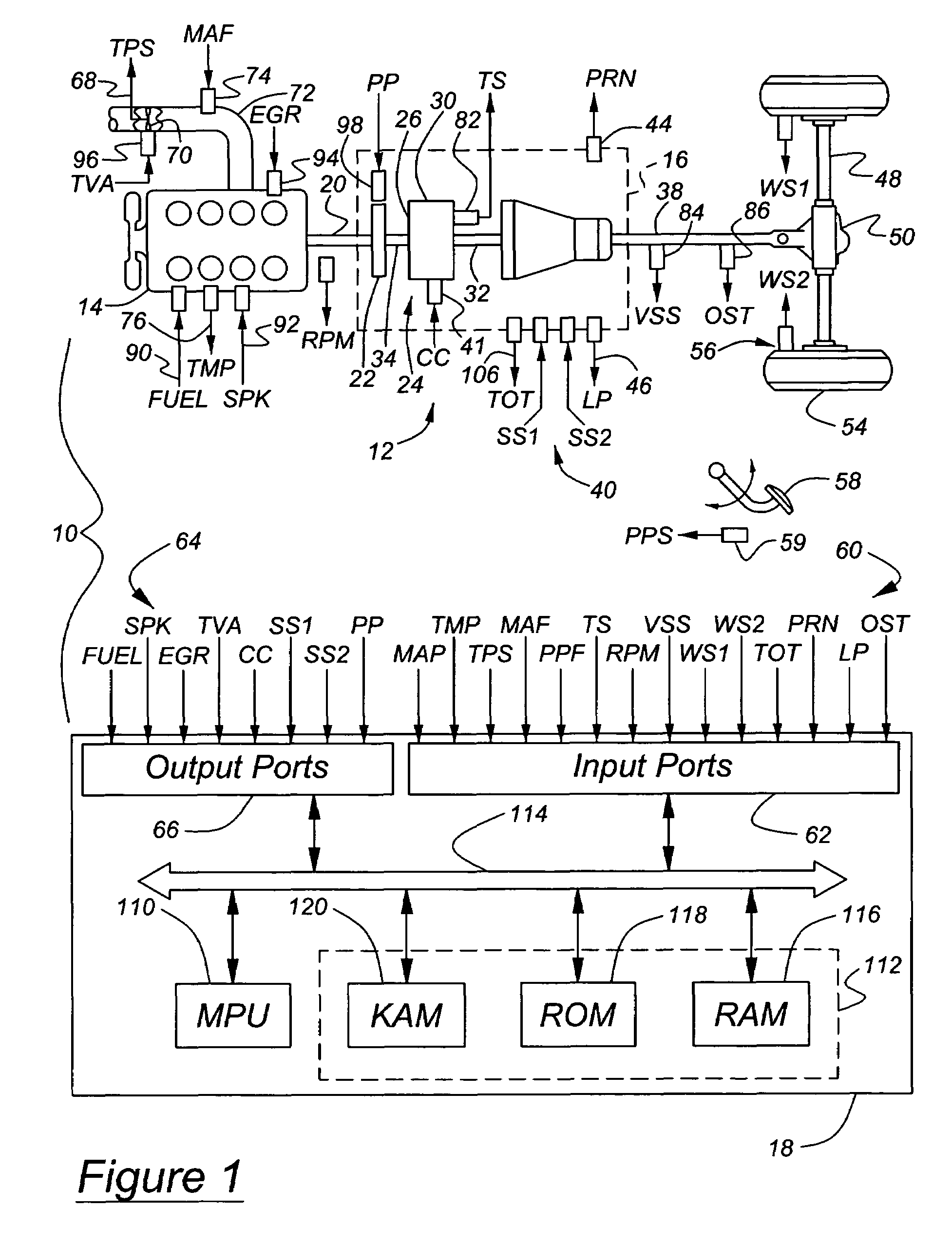
[0014]FIG. 1 is a block diagram illustrating a system 10 for controlling the shifting process downshifts of an automatic transmission according to the present invention. System 10 includes a vehicle power train 12 having an internal combustion engine 14 coupled to an automatic transmission 16. Powertrain 12 may also include a controller 18 in communication with engine 14 and transmission 16 for providing various information and control functions. Engine 14 is connected to transmission 16 via a crankshaft 20, which is connected to transmission pump 22 and / or a torque converter 24. Preferably, torque converter 24 is a hydrodynamic torque converter including an impeller 26, which is selectively, hydrokinetically coupled to a turbine 28. Torque converter 24 may also include a hydraulically actuated friction converter clutch or bypass clutch 30, which releasably connects the turbine shaft 32 and crankshaft 20.

[0015]Automatic transmission 16 produces multiple gear ratios by selectively en...


PUM


Abstract

An automatic transmission ratio shift and shift feel control system and method for a powertrain having an engine, multiple-ratio gearing controlled by friction elements actuated by hydraulic pressure, an output shaft torque sensor producing a signal representing the magnitude of current output torque, an electronic controller for controlling the target output torque based on the current output torque, increasing the torque capacity of the oncoming friction element and decreasing the torque capacity of the offgoing friction element after a gear ratio change is initiated. During the inertia phase of the ratio change, the controller controls the engine speed to follow a predetermined rate of change of input speed. The strategy employs an electronic throttle and closed loop engine torque control and closed loop engine speed control at various phases of the gear shift, to improve shift feel. Various engine parameters, including throttle position, ignition timing, engine air-fuel ratio, and engine airflow, control engine torque and speed, are used to control input torque or input speed, depending upon the shift phase.

Description

BACKGROUND OF THE INVENTION[0001]The invention relates to a system and method for controlling gear shifts in a vehicle power train that includes an engine and an automatic transmission capable of producing multiple gear ratios.[0002]Because shift quality control in automatic transmissions for motor vehicles is attempted using incomplete information from power train sensors, the quality of gear shifts, often called shift feel, produced by automatic transmissions operating under electronic control that employ conventional control strategies often lacks the desired smoothness. There is a continual need to minimize the torque disturbance at the output shaft of an automatic transmission caused by gear shifts. This disturbance often produces noise, vibration and harshness, which is felt by vehicle occupants.[0003]Currently, the primary sensor information used in gear shift control is the transmission input speed and output speed. This information is indirectly used to infer and to control...

Claims


Application Information

Patent Timeline
Patent Type & Authority Patents(United States)
IPC IPC(8): B60W10/04B60W10/00B60W30/18F16H61/06F16H63/50
CPCF16H61/061F16H63/502B60W30/18B60K2741/065Y10T477/693965B60W2520/10B60W2540/10B60W2710/027B60W2710/0605B60W2710/0622B60W2710/0644B60W2710/0666F16H2306/42F16H2306/44F16H2306/52Y10T477/679Y10T477/68Y10T477/6418B60W10/04B60W10/11B60W30/1819
Inventor COWAN, RONALD
Owner FORD GLOBAL TECH LLC
Why Eureka
Try Eureka