Device and method for reducing corneal induced aberrations during ophthalmic laser surgery

a technology of ophthalmic laser surgery and device, applied in the field of surgical devices, can solve the problems of beam distortion, loss of focal spot definition, etc., and achieve the effect of reducing or eliminating optical aberrations

Inactive Publication Date: 2006-01-31
AMO DEVMENT
View PDF25 Cites 48 Cited by
  • Summary
  • Abstract
  • Description
  • Claims
  • Application Information

AI Technical Summary

Benefits of technology

[0008]In one embodiment for the present invention, a lens for use in ophthalmic laser surgery includes an optical element in combination with a suction means. More specifically, the suction means is connected in fluid communication with the optical element to selectively create a partial vacuum between the optical element and the cornea when the lens is positioned over an eye. In response to the partial vacuum, the cornea is forced against the optical element. This reconfigures the cornea for laser surgery and thereby reduces or eliminates optical aberrations that would otherwise be caused by the natural shape of the cornea.
[0009]In more detail, the optical element of the present invention includes a lens member which has two opposed surfaces; a substantially flat anterior surface and a substantially flat or slightly curved contact surface. Specifically, as intended for the present invention, the contact surface can be shaped flat or slightly curved to cause the shape of the anterior surface of the cornea to change when the anterior surface of the cornea is held against the contact surface. Preferably, the lens member is made of a substantially clear, medical grade plastic. Additionally, a skirt surrounds the contact surface and extends outwardly therefrom to establish and surround a recessed chamber and define an opening to the recessed chamber. In the preferred embodiment, the skirt is formed with a sealing surface for contacting the cornea. The sealing surface of the skirt is preferably formed having a concave shape extending into the recess. The concave shape of the sealing surface allows the skirt to establish a seal with the cornea when the lens is placed against the eye. Preferably, the sealing surface of the skirt is made of a soft medial grade plastic to further facilitate a strong seal between the skirt and the cornea during use. Inside the recessed chamber, a suction channel is provided at the interface between the contact surface and the skirt.
[0011]As intended for the present invention, the lens can be mounted on a retainer ring which is attached to the laser system that is being used. More specifically, the retainer ring holds the lens in a predetermined orientation relative to the laser system so that the laser surgery can be performed.
[0012]In the operation of the present invention, the aplanatic lens is positioned over the eye so that the cornea of the eye is covered by the opening into the recessed chamber. The suction device is then activated to create a partial vacuum in the chamber. Due to this partial vacuum, the cornea is pulled or drawn into the chamber. Specifically, the cornea is flattened against the contact surface of the optical element. As indicated above, with the flattening of the cornea, spherical aberrations and comas which would otherwise be caused by the spherical geometry of the cornea are reduced or eliminated. After the particular ophthalmic laser procedure has been completed, the suction device is deactivated, the partial vacuum is dissipated, and the aplanatic lens is removed from the eye. The lens can be discarded and another new aplanatic lens may be used for the next patient.

Problems solved by technology

Unfortunately, since the anterior surface of the cornea in its natural state is nearly spherical, once a beam of light passes through the anterior surface of the cornea, aberrations are introduced into the beam that cause the beam to distort.
For light beams that are focused to a focal spot within the cornea, both spherical aberration and coma cause a loss of definition of the focal spot.

Method used


Image

  • Device and method for reducing corneal induced aberrations during ophthalmic laser surgery
  • Device and method for reducing corneal induced aberrations during ophthalmic laser surgery
  • Device and method for reducing corneal induced aberrations during ophthalmic laser surgery

Examples


Embodiment Construction

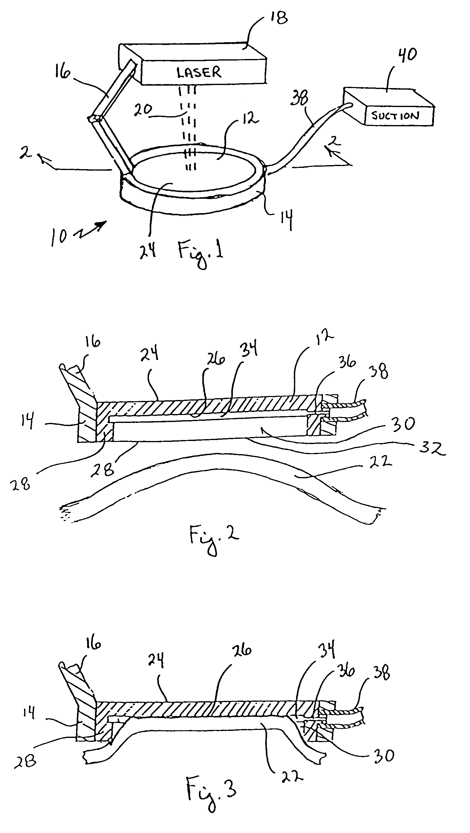
[0026]Referring initially to FIG. 1, a lens system in accordance with the present invention is shown and generally designated 10. As shown, the system 10 includes a lens member 12 which is mounted on a retainer ring 14. Further, the retainer ring 14 is adjustably connected via an extension arm 16 to a laser source 18. For purposes of the present invention, the laser source 18 is activated to generate a laser beam 20 which is directed through the lens member 12. As will become more apparent with further disclosure, the lens member 12 is configured to eliminate, or substantially reduce any spherical aberration or coma that may otherwise have been caused by the spherical nature of the cornea 22 of an eye.

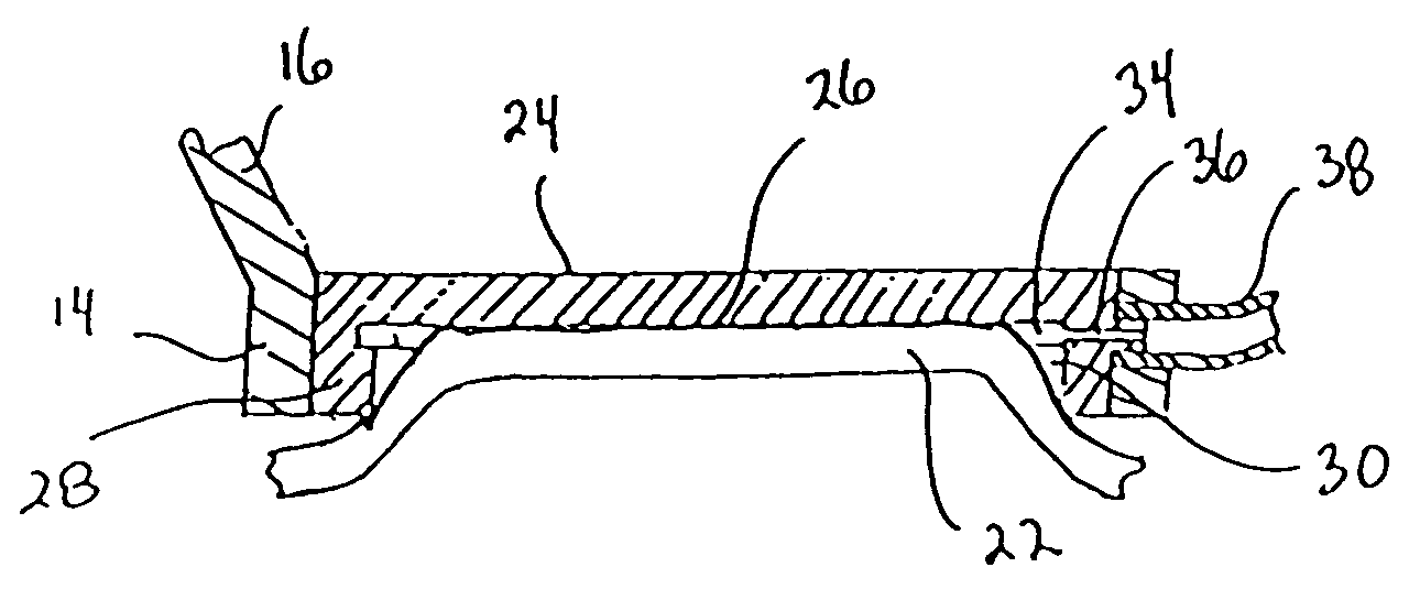
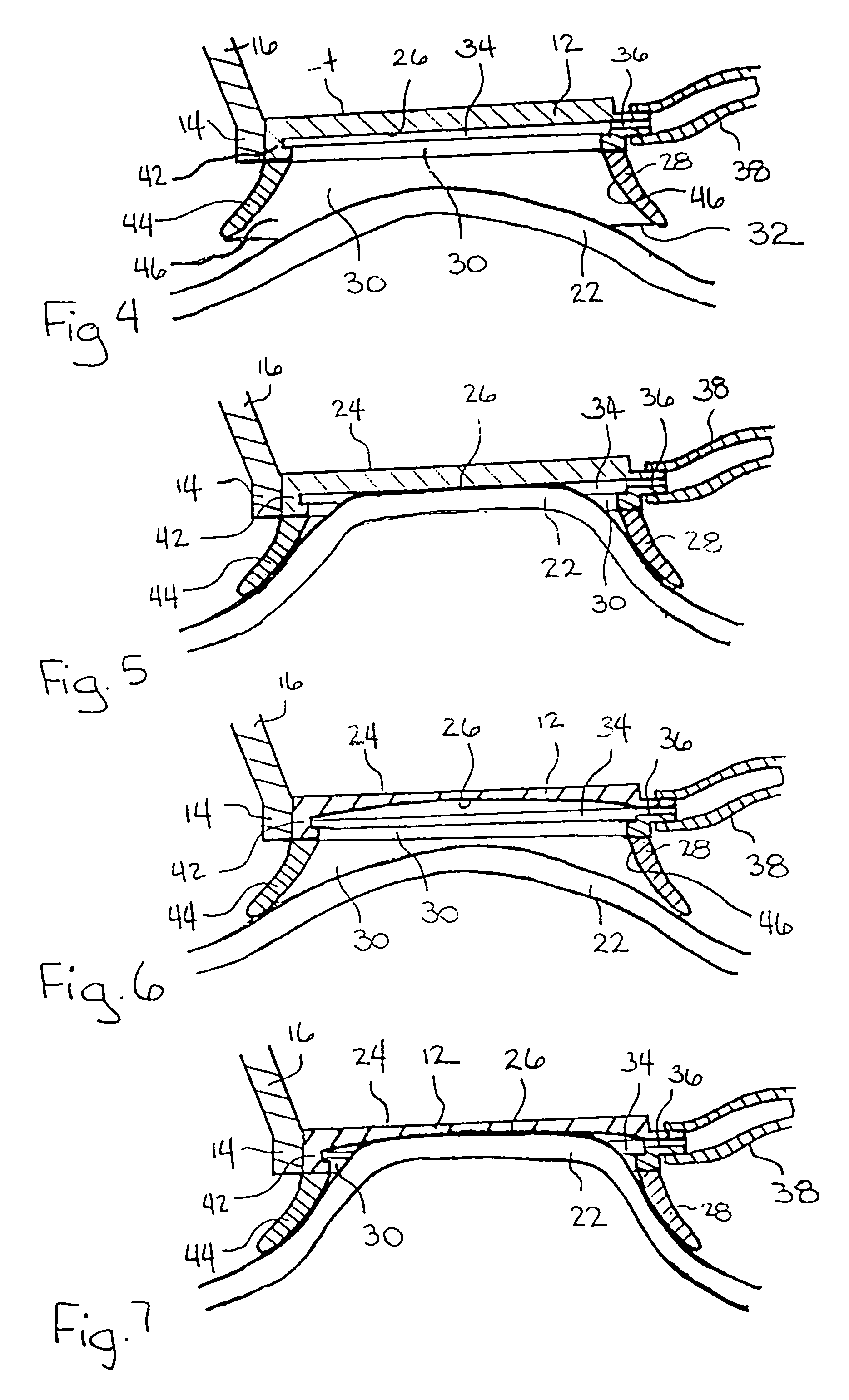
[0027]The actual structure of the lens member 12 will perhaps be best appreciated by reference to FIG. 2 wherein it will be seen that the lens member 12 is formed with an anterior surface 24 and a contact surface 26. It is to be appreciated that the anterior surface 24 can be substanti...


PUM


Abstract

A disposable lens for reconfiguring the cornea of an eye for ophthalmic laser surgery includes a lens which has a flat anterior surface that is formed opposite a contact surface. A skirt surrounds the contact surface and extends outwardly therefrom to define a chamber. The skirt is formed with a groove which creates a suction channel between the skirt and the contact surface in the chamber. In its operation, the lens is positioned over the cornea and a vacuum pump is selectively activated to create a partial vacuum in the suction channel. Due to this partial vacuum, the cornea is drawn into the chamber where it is urged against the contact surface of the lens. The result of this is that the cornea is flattened into a configuration where the introduction of spherical aberration and coma into a light beam passing into the cornea is reduced or eliminated.

Description

[0001]This application is a continuation application of application Ser. No. 09 / 834,979 filed on Apr. 13, 2001, now U.S. Pat. No. 6,623,476, which is a continuation-in-part of application Ser. No. 09 / 172,819, filed Oct. 15, 1998, now U.S. Pat. No. 6,254,595. The contents of application Ser. No. 09 / 834,979 and application Ser. No. 09 / 172,819 are incorporated herein by reference.FIELD OF THE INVENTION[0002]The present invention pertains generally to surgical devices. More particularly, the present invention pertains to surgical lenses which are used in ophthalmic laser surgery. The present invention is particularly, but not exclusively, useful as a lens for temporarily reconfiguring the cornea from an imperfect shape which causes light passing through the cornea to experience aberration into a shape that allows light to pass through the cornea with little or no aberration.BACKGROUND OF THE INVENTION[0003]For ophthalmic laser procedures involving the photodisruption of eye tissue, it i...

Claims


Application Information

Patent Timeline
Patent Type & Authority Patents(United States)
IPC IPC(8): A61B18/20A61F9/007A61F9/009A61F9/01G02C7/04
CPCA61F9/009A61F2009/00872
Inventor JUHASZ, TIBORKURTZ, RONALD M.SUAREZ, CARLOS G.
Owner AMO DEVMENT
Why Eureka
Try Eureka