Radome

Inactive Publication Date: 2006-01-31
MITSUBISHI ELECTRIC CORP
View PDF8 Cites 20 Cited by
  • Summary
  • Abstract
  • Description
  • Claims
  • Application Information

AI Technical Summary

Benefits of technology

[0011]As mentioned above, according to the present invention, it is arranged that the wall of a radome have a structure in which a skin portion, a core portion, a high relative-dielectric-constant layer, another core portion, and another sk

Problems solved by technology

In a radome having an aerodynamic shape providing a small resistance to the air in contrast to a ground radome having a hemispherical shape, the angle of incidence of the electromagnetic wave on the wall of the radome is not uniform.
In general, when the electromagnetic wave impinges on the wall of the radome at a large angle to the wall, the loss thereof is large.
Therefore, in the radome having an aerodynamic shape, constructed according to a conventional technology, there is the problem that the tr

Method used


Image

  • Radome
  • Radome
  • Radome

Examples


embodiment 1

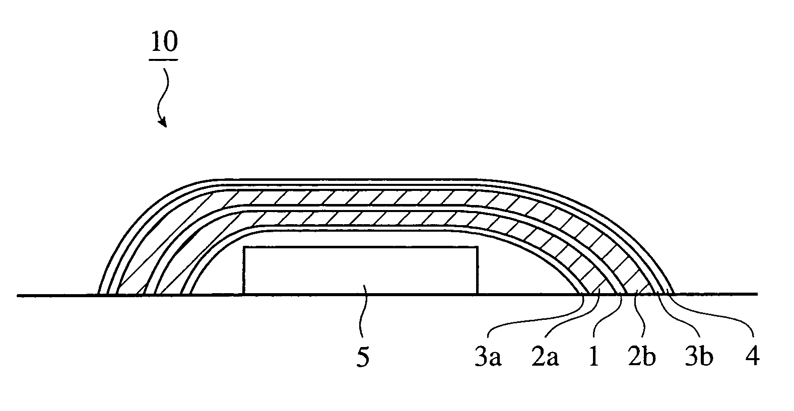
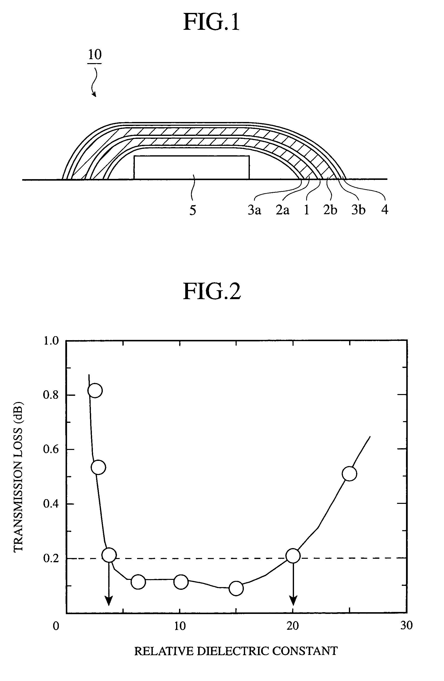
[0016]A radome 10 according to a first embodiment of the present invention will be described by referring to FIG. 1 and FIG. 2. FIG. 1 is a view for explaining the radome 10 according to the first embodiment of the present invention. FIG. 2 is a diagram for explaining the dependence of the transmission loss to the relative dielectric constant of a high relative-dielectric-constant layer over a range of the angle of incidence of 0°–70° in the first embodiment.

[0017]As shown in FIG. 1, the radome 10 according to the first embodiment has a structure in which core portions (core material) 2a, 2b are laminated to the one side surface and the other side surface of a high relative-dielectric-constant layer 1, respectively, and skin portions (skin portion) 3a, 3b are additionally laminated to the one side surface and the other side surface of the obtained laminated material, respectively. Moreover, the skin portion 3b laminated to the outside surface of the obtained laminated material is co...

embodiment 2

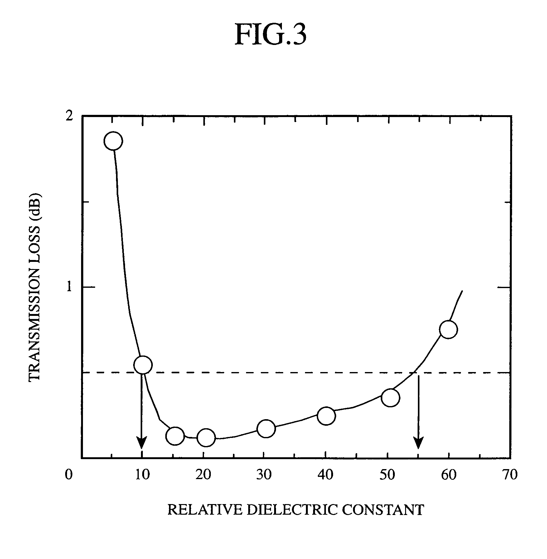
[0030]A radome according to a second embodiment of the present invention will be described by referring to FIG. 3. In the second embodiment, the optimum value of the relative dielectric constant of the high relative-dielectric-constant layer was determined when the difference in relative dielectric constant between the skin portion and the core portion was more than 1.5 (although, in the first embodiment, the optimum value of the relative dielectric constant thereof was determined when the difference was 1.5 or less). FIG. 3 is a diagram for explaining the dependence of the transmission loss to the relative dielectric constant of a high relative-dielectric-constant layer over a range of the angle of incidence of 0°–70° in the second embodiment. Since the configuration and the manufacturing process of the radome according to the second embodiment are similar to the configuration and the process, respectively, described by referring to FIG. 1 in the first embodiment, the explanation i...


PUM


Abstract

A radome has a structure in which core portions are laminated to opposite side surfaces of a high relative-dielectric-constant layer, respectively, and skin portions are additionally laminated to opposite side surfaces of the laminate, respectively. Furthermore, the skin portions laminated to the outside surfaces are coated with a coating material. The radome accommodates an antenna. The high relative-dielectric constant layer has a relative dielectric constant that is larger than the relative dielectric constants of the skin portions, and of the core portions.

Description

BACKGROUND OF THE INVENTION[0001]1. Field of the Invention[0002]The present invention relates to a radome that accommodates a radar, and more particularly the invention relates to a radome that is installed in an aircraft, a vehicle, or the like, and that has an aerodynamic shape.[0003]2. Description of the Related Art[0004]With recent improvements in communication technology and information processing technology, a technology for two-way communicating from an aircraft, a vehicle, or the like is being placed in practical use. Particularly for the aircraft, in order to communicate from an installed antenna system therein through the medium of satellites, a wider beam scanning range than the conventional is demanded. Therefore, it is required of the radome that the loss of an electromagnetic wave caused by the reflection of the wave input and output by the antenna be small on the wall of the radome over the wider range of the antenna scanning angle.[0005]In a radome having an aerodyna...

Claims


Application Information

Patent Timeline
IPC IPC(8): H01Q1/42H01Q1/28H01Q1/32
CPCH01Q1/28H01Q1/422H01Q1/32
Inventor USAMI, RYOOZAKI, TSUYOSHITSURUTA, JUN
Owner MITSUBISHI ELECTRIC CORP
Why Eureka
Try Eureka