Buffer occupancy used in uplink scheduling for a communication device

a communication device and buffer occupancy technology, applied in the field of wireless communication devices, can solve the problems of time synchronization of the base station not always readily accommodated, asynchronous transmissions are not without their own set of concerns, and problems such as site diversity

Inactive Publication Date: 2006-01-31
GOOGLE TECH HLDG LLC
View PDF8 Cites 188 Cited by
  • Summary
  • Abstract
  • Description
  • Claims
  • Application Information

AI Technical Summary

Problems solved by technology

However, with the increasing amount of demand for data transfer (bandwidth), problems can arise.
However, because line of sight transmissions are not always possible for base stations that might be located within buildings or tunnels, or base stations that may be located under the ground, sometimes the time synchronization of the base stations is not always readily accommodated.
However, asynchronous transmissions are not without their own set of concerns.
Furthermore, in the event of a collision, there is spare bandwidth available to accommodate the need for any retransmissions.
However, as traffic volume increases, the likelihood of data collisions (overlap) also increases.
The need for any retransmissions also correspondingly increases, and the availability of spare bandwidth to support the increased amount of retransmissions correspondingly diminishes.
However even with explicit scheduling, given the disparity of start and stop times of asynchronous communications and more particularly the disparity in start and stop times relative to the start and stop times of different uplink transmission segments for each of the non-synchronized base stations, gaps and overlaps can still occur.
This however potentially leads to several issues.
Firstly, a non-scheduling BTS may schedule the MS based on outdated buffer occupancy reports received prior to the last successful scheduling of the MS.
In addition, due to multiple schedulers ...

Method used


Image

  • Buffer occupancy used in uplink scheduling for a communication device
  • Buffer occupancy used in uplink scheduling for a communication device
  • Buffer occupancy used in uplink scheduling for a communication device

Examples


Embodiment Construction

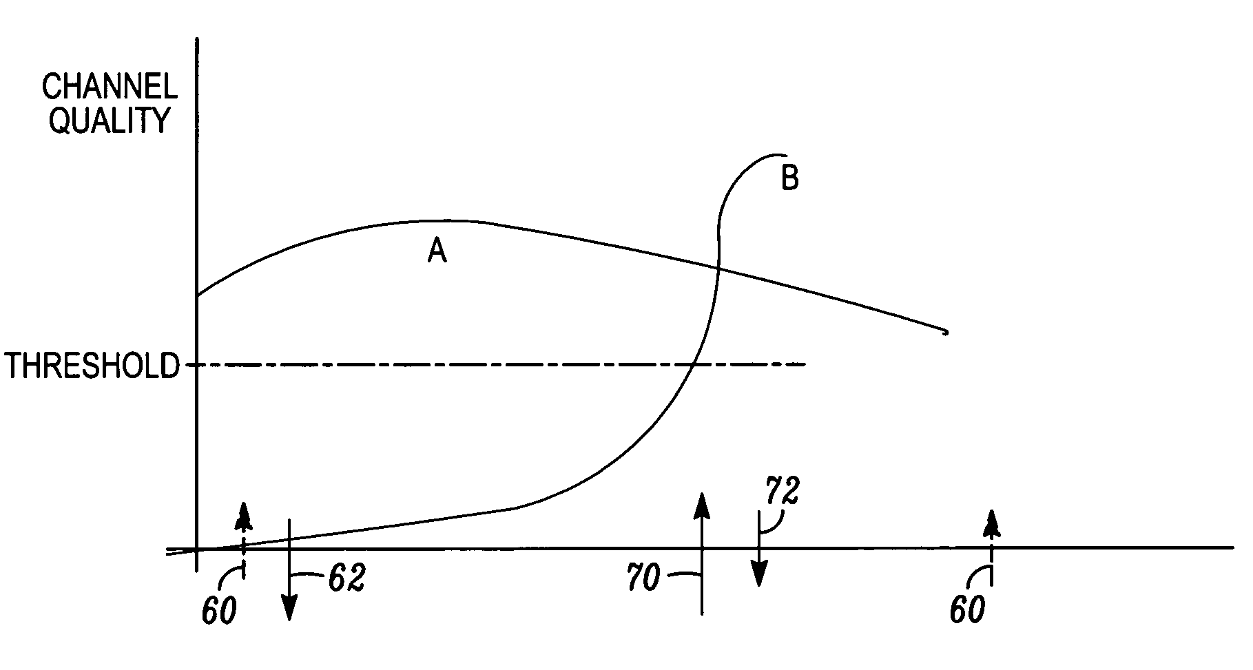
[0032]The present invention provides novel techniques to ensure that BTSs receive reliable buffer occupancy information, such that a macro selection diversity benefit is obtained. In one aspect of the present invention, time-stamping of the last transmission opportunity along with buffer occupancy is reported so that BTSs have the latest information that can assist it in ensuring a higher degree of fairness. Another aspect of the present invention provides the last known transmission opportunity to the BTS when first added to the active set of the mobile, since it is likely that this BTS may schedule the mobile early on, to help it initialize its fairness setting. Another aspect of the present invention transmits a buffer occupancy report when the mobile determines that a BTS has exceed a certain predetermined uplink channel quality and is therefore most likely to schedule the mobile. Additional information such as persistence of fading, speed, distance from BTS, etc., could be sent...


PUM


Abstract

A method for using buffer occupancy in uplink scheduling for a communication device includes a first step of sending buffer occupancy information and a time stamp indicating a last transmission opportunity provided to the communication device to an active set base stations. A next step includes utilizing the buffer occupancy information and time stamp to adjust a scheduling fairness setting for the communication device. A next step includes receiving scheduling information from a scheduler in accordance with the scheduling fairness setting. A next step includes transmitting on an uplink channel in accordance with the scheduling information.

Description

FIELD OF THE INVENTION[0001]The present invention relates generally to a wireless communication device, and more specifically to fairness in uplink scheduling of a communication device.BACKGROUND OF THE INVENTION[0002]In a Universal Mobile Telecommunications System (UMTS), such as that proposed for the next of the third generation partnership project (3GPP) standards for the UMTS Terrestrial Radio Access Network (UTRAN), such as wideband code division multiple access (WCDMA) or cdma2000 for example, user equipment (UE) such as a mobile station, (MS) communicates with any one or more of a plurality of base station subsystems (BSSs) dispersed in a geographic region. Typically, a BSS (known as Node-B in WCDMA) services a coverage area that is divided up into multiple sectors (known as cells in WCDMA). In turn, each sector is serviced by one or more of multiple base transceiver stations (BTSs) included in the BSS. The mobile station is typically a cellular communication device. Each BTS...

Claims


Application Information

Patent Timeline
IPC IPC(8): H04Q7/20H04L12/28H04L12/56H04W72/12
CPCH04W72/1284H04B7/022H04W72/1257H04W72/1252H04W72/52H04W72/535H04W72/21H04L47/30
Inventor KUCHIBHOTLA, RAVILOVE, ROBERT T.
Owner GOOGLE TECH HLDG LLC
Why Eureka
Try Eureka