
Method and apparatus for predicting the time to failure of electronic devices at high temperatures

Active Publication Date: 2006-01-31
SCHLUMBERGER TECH CORP
View PDF20 Cites 23 Cited by
  • Summary
  • Abstract
  • Description
  • Claims
  • Application Information

AI Technical Summary

Problems solved by technology

Neither the computer nor communications industries typically have a need to operate electronic devices above 85° C. While there are a few industries, for example, the automobile, aerospace, and oil industries, that have a need to operate electronic devices at such higher temperatures, none of these industries purchase electronic devices in volumes that influence the electronics manufacturers to design electronic devices that operate at such higher temperatures.
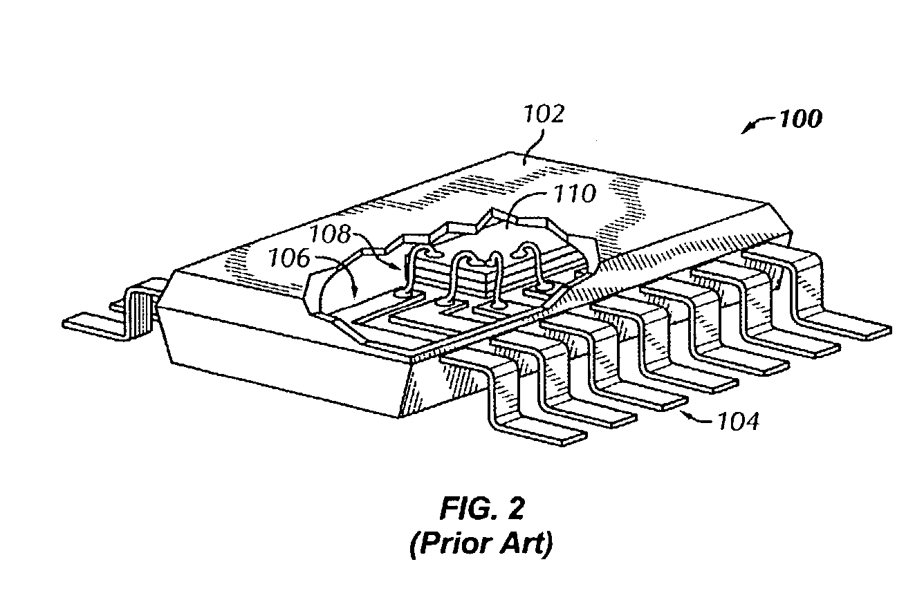
When electronic devices, for example the plastic encapsulated integrated circuit (100 shown in FIG. 2), are operated at high temperature, chemical reactions may cause internal failures to be accelerated and cause premature failure.
Furthermore, thermal expansion of dissimilar materials may result in high stresses to develop and cause failure.
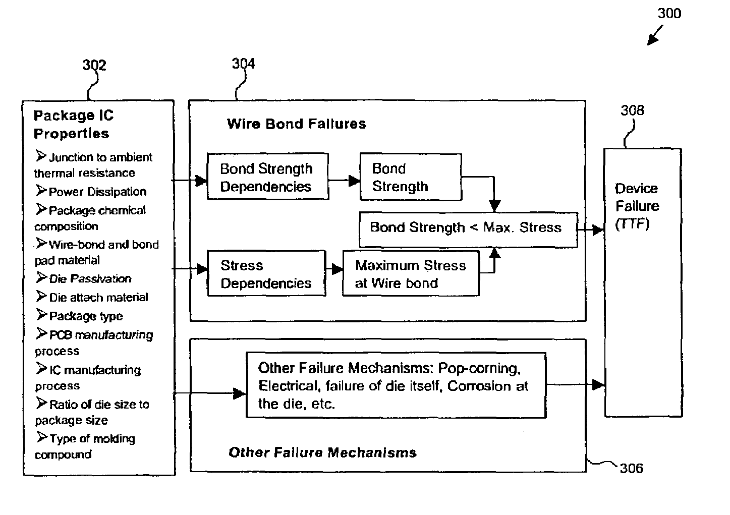
Both the weakening of the wire bond strength due to corrosion reactions combined with high stresses due to coefficient of thermal expansion (CTE) mismatches in the materials within the plastic encapsulated integrated circuit (100) lead to premature failure.
Several researchers have found that halogens such as Br, Cl, and Fl introduced into the molding compound as flame-retardants accelerate inter-metallic formation and cause voiding and corrosion leading to wire bond failure.
Antimony was also found to accelerate wire bond failures and may affect the wire bonds independently of Br.
A change in construction of a plastic encapsulated integrated circuit (e.g., 100 shown in FIG. 2) is, however, not a practical solution since a manufacturing process of an electronic device is unlikely to be influenced for the reasons discussed above.
When electronic devices are operated at higher temperatures, however, a failure of the electronic devices may be accelerated.

Method used


Image

  • Method and apparatus for predicting the time to failure of electronic devices at high temperatures
  • Method and apparatus for predicting the time to failure of electronic devices at high temperatures
  • Method and apparatus for predicting the time to failure of electronic devices at high temperatures

Examples


Embodiment Construction

[0021]Embodiments of the present invention include methods for predicting time to failure (TTF) of an electronic device, such as a plastic encapsulated integrated circuit, when used at temperatures beyond the electronics manufacturer's recommended operating temperature range. A method in accordance with the invention includes a model of failure mechanisms, which relate a series of measurable parameters representing independent variables to predict a time to failure of electronic devices. The model lends itself to algorithmic representation that can be implemented in software operated on a computer system.

[0022]The invention described here may be implemented on virtually any type of computer regardless of the platform being used. For example, as shown in FIG. 3, a typical computer (200) has a processor (202), associated memory (204), and numerous other elements and functionalities typical to today's computers (not shown). The computer (200) has associated therewith input means such a...


PUM


Abstract

A method and apparatus are disclosed for determining a time to failure for an electronic device. The method and apparatus includes estimating a dependency of a bond strength degradation rate on at least one parameter and estimating a temperature profile of the electronic device. Furthermore, the method and apparatus determine a bond strength based on the dependency of the bond strength degradation rate and the temperature profile, and determine the time to failure for the electronic device based on a time evolution of the bond strength.

Description

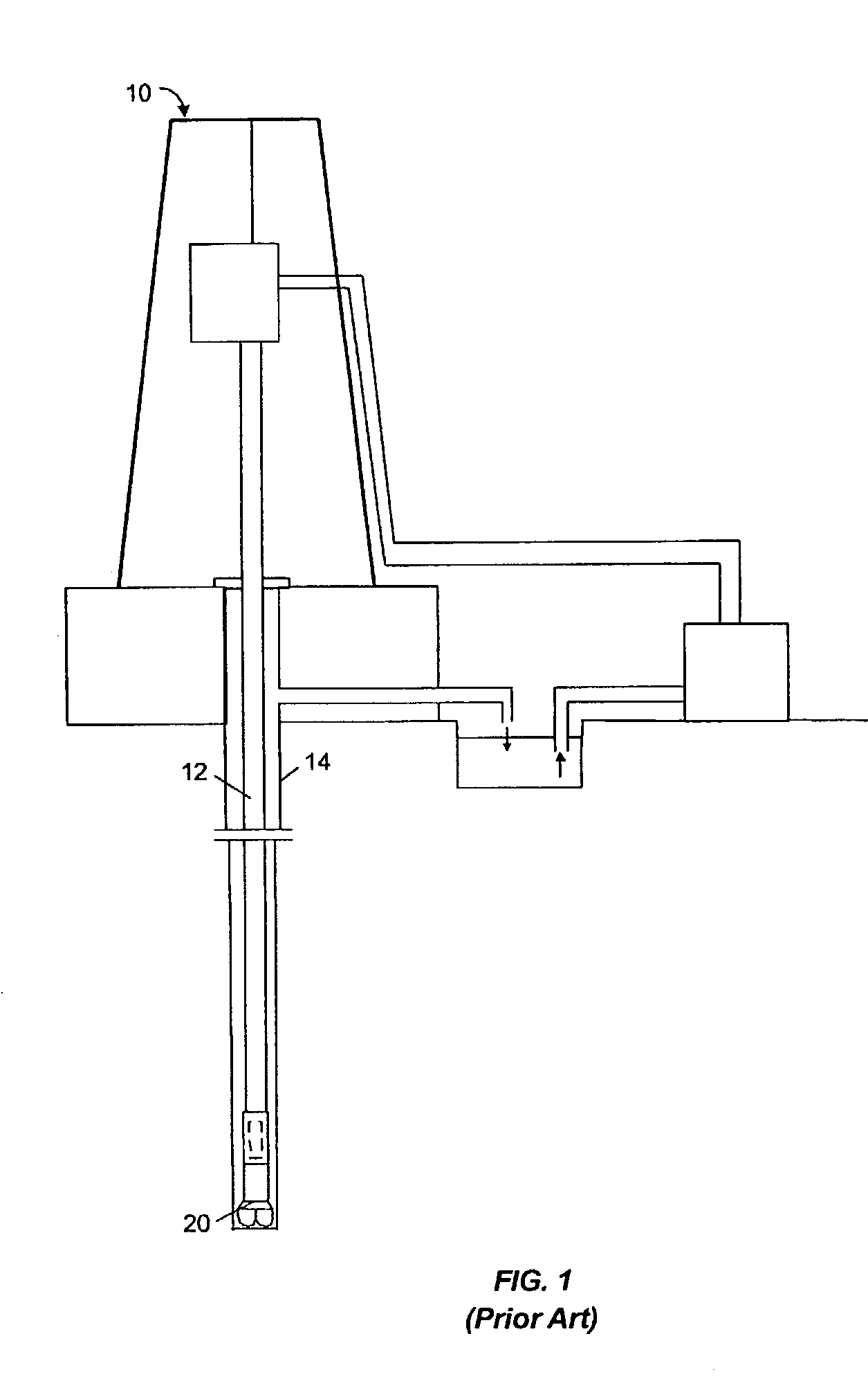
BACKGROUND OF INVENTION[0001]FIG. 1 shows one example of a conventional drilling system for drilling a well bore in an earth formation. The drilling system includes a drilling rig (10) used to turn a drill string (12), which extends downward into a well bore (14). Connected to the end of the drill string (12) is a drill bit (20).[0002]In drilling applications, electronic devices may be used downhole to acquire information about the drilling operation and / or the earth formation. The electronic devices may need to be operated at temperatures much higher than their rated operational range. As the wells are drilled deeper, the desired operating temperature range for the electronic devices increases.[0003]The electronic devices market is driven primarily by the computer and communications industries. Neither the computer nor communications industries typically have a need to operate electronic devices above 85° C. While there are a few industries, for example, the automobile, aerospace, ...

Claims


Application Information

Patent Timeline
IPC IPC(8): G01R31/00G01R31/28
CPCG01R31/2858G01R31/287H01L2224/48247H01L2924/181H01L2924/00012
Inventor GUNAWARDANA, RUVINDAETCHELLS, RICHARD K.
Owner SCHLUMBERGER TECH CORP
Learn More