
Wrench having angle adjustable handle

a technology of adjustable handle and wrench, which is applied in the field of wrenches, can solve the problems of increasing the driving instability of the driving cartridge by the handle, the spool may have a good chance of being easily forced to move out of or be disengaged from the tool head, and the use of the push button for suitably locking and unlocking the tool head with the catch

Inactive Publication Date: 2006-02-07
KAO CHEIN CHUAN +1
View PDF7 Cites 41 Cited by
  • Summary
  • Abstract
  • Description
  • Claims
  • Application Information

AI Technical Summary

Benefits of technology

[0015]The tool head includes an enlarged peripheral shoulder formed therein and located around the chamber thereof, and a cap secured to the shaft and rotatably seated and engaged in the peripheral shoulder of the tool head, to rotatably anchor said cap to the tool head. The follower includes a substantially rectangular structure, for snugly fitting in the channel of the shaft and between the arms of the shaft, to prevent the follower from sliding sidewise relative to the shaft.

Problems solved by technology

However, the engagement of the teeth of the spool with the corresponding teeth of the hub of the tool head is similar to the typical ratchet mechanism for tools, and the spool may be easily forced to move along a longitudinal axis of the spool that is perpendicular to the tool head, and the spool is parallel to the rotational or moving plane of the handle, such that the spool may have a good chance to be easily forced to move out of or to be disengaged from the tool head when the handle is rotated relative to the tool head.
However, the push button is rotatably and slidably engaged in the transverse hole of the handle, and thus may have a good chance to be rotated relative to the handle, and thus to disengage the projected supporting surface from the catch, and such that the push button may not be used for suitably locking and unlocking the tool head with the catch.
However, the provision and the engagement of the pawl and the barrel between the driving cartridge and the handle may increase the distance between the driving cartridge and the handle, and thus may increase the driving instability of the driving cartridge by the handle.

Method used


Image

  • Wrench having angle adjustable handle
  • Wrench having angle adjustable handle
  • Wrench having angle adjustable handle

Examples


Embodiment Construction

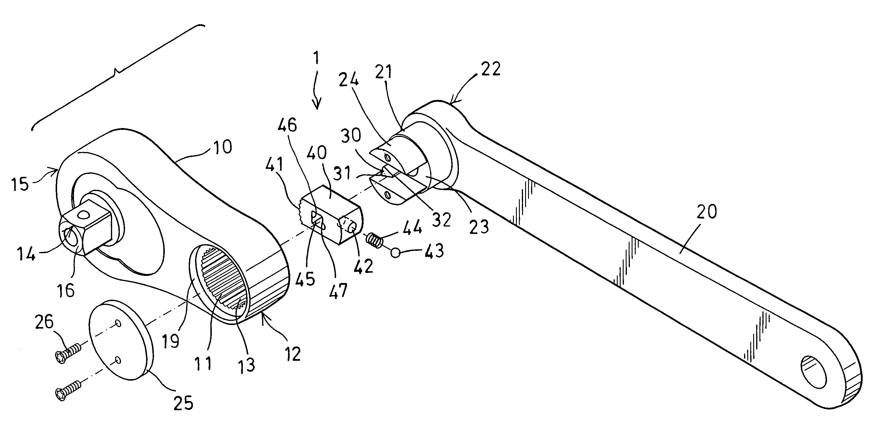
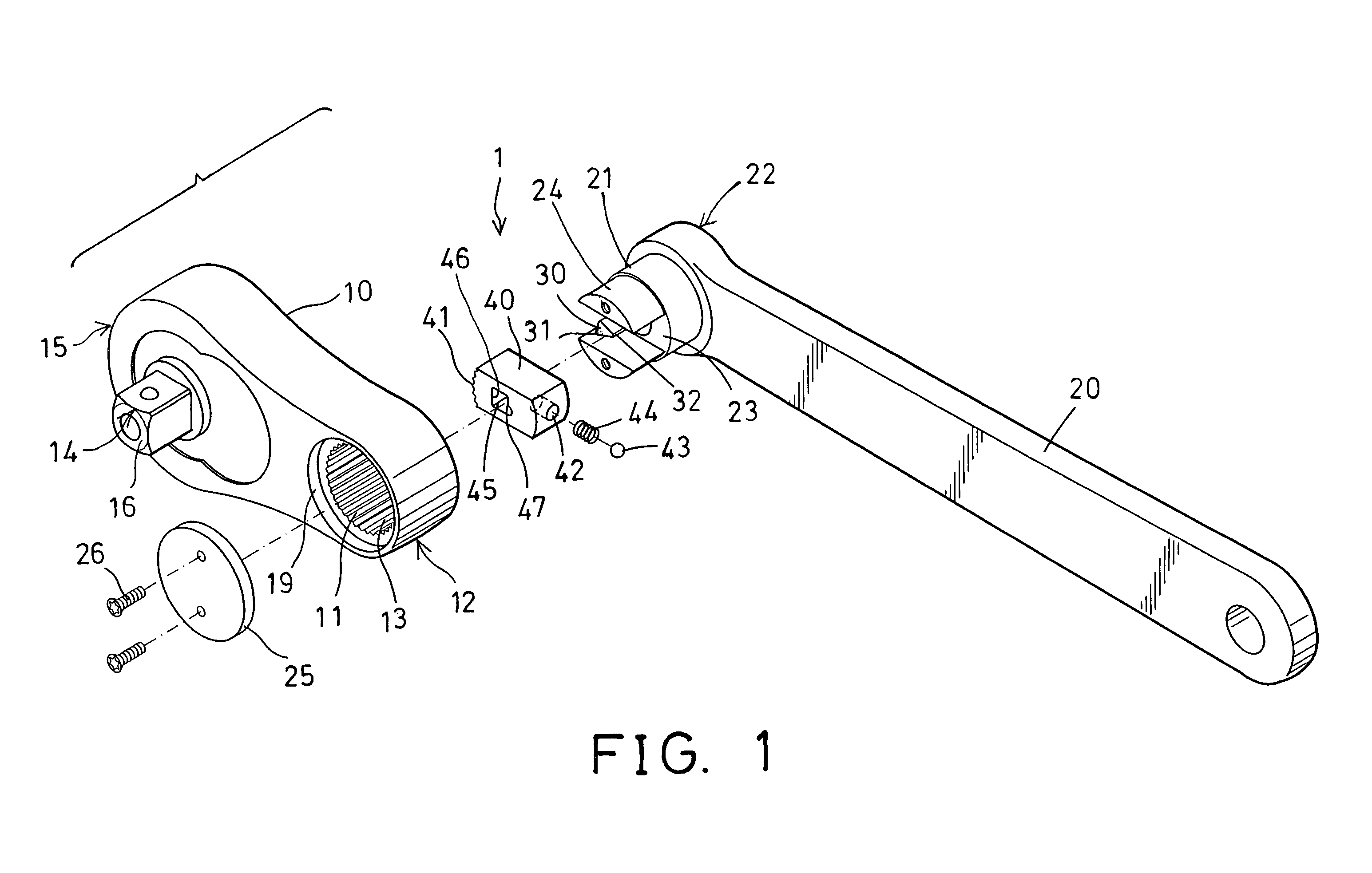
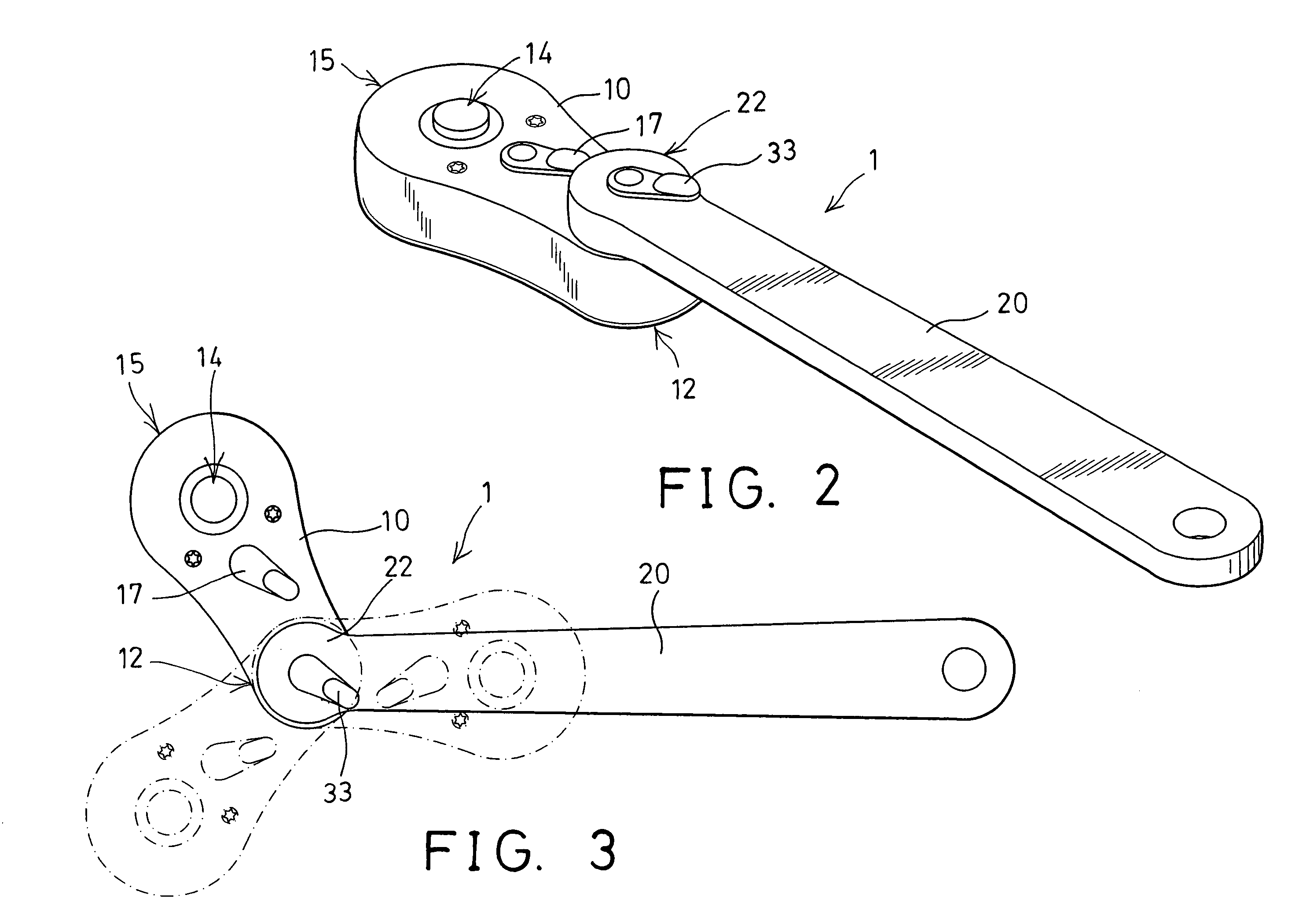
[0025]Referring to the drawings, and initially to FIGS. 1–7, a wrench 1 in accordance with the present invention comprises a tool head 10 including a chamber 11 formed therein, such as formed in the rear portion 12 thereof, and having a number of teeth 13 formed therein, and including a driving mechanism 14 provided within the tool head, such as provided in the front portion 15 thereof, and having a driving shank 16 extended therefrom (FIGS. 1, 6, 7), for engaging with and for driving fasteners, tool extensions, sockets and tool bits, or other tool members.

[0026]Normally, the driving mechanism 14 includes a knob 17 extended out of the tool head 10, and coupled to an inner pawl (not shown), for controlling the driving direction of the driving mechanism 14. Alternatively, the driving mechanism 14 may include an engaging hole 18 formed therein, as shown in FIG. 8, for receiving and for driving fasteners, tool extensions, sockets and tool bits, or other tool members. The above-described...


PUM


Abstract

A wrench includes a tool head having a number of teeth formed in a chamber, and a handle having a shaft rotatably engaged into the chamber of the tool head and having a channel laterally formed in the shaft, a stem is engaged into the channel of the shaft, and includes one or more actuators. A follower is slidably received in the channel of the shaft, and includes one or more teeth for engaging with the teeth of the tool head, and for selectively locking the handle to the tool head at selected angular position. The follower includes a space formed by an inner peripheral surface, for engaging with the actuators. One of the actuators may force the teeth of the follower to solidly engage with the teeth of the tool head.

Description

BACKGROUND OF THE INVENTION[0001]1. Field of the Invention[0002]The present invention relates to a wrench, and more particularly to a wrench having a pivotal handle adjustable to various angular position relative to the driving cartridge or the driving head.[0003]2. Description of the Prior Art[0004]Typical flex-head wrenches comprise a handle pivotally connected to a tool head, and a locking mechanism having a unitary locking spool seated within the handle and manipulated to lock or unlock the tool head at a desired angular position with respect to the handle.[0005]For example, U.S. Pat. No. 5,199,335 to Arnold et al. discloses one of the typical flex-head wrenches comprising a unitary locking spool seated within a handle and having a cooperating series of teeth extending around a portion of the spool, for engaging with the corresponding teeth of a hub of the tool head, to lock the handle to the tool head in place.[0006]However, the engagement of the teeth of the spool with the cor...

Claims


Application Information

Patent Timeline
Patent Type & Authority Patents(United States)
IPC IPC(8): B25B23/16B25B1/00B25B13/46B25G3/28F16C11/00
CPCB25B13/46B25B13/461B25B23/0028B25G1/063Y10T403/32368Y10T403/32418Y10T403/7026
Inventor KAO, CHEIN CHUANCHEN, CHIA YU
Owner KAO CHEIN CHUAN
Features
  • Generate Ideas
  • Intellectual Property
  • Life Sciences
  • Materials
  • Tech Scout
  • Unparalleled Data Quality
  • Higher Quality Content
  • 60% Fewer Hallucinations
Learn More