Magnetic tape manufacturing apparatus

a manufacturing apparatus and magnetic tape technology, applied in the direction of transportation and packaging, web handling, mechanical tension control of carriers, etc., can solve the problems of poor running of magnetic tapes, variations in the tape width of magnetic tape products, and lack of magnetic tapes or the generation of extreme tension in magnetic tapes, so as to improve yield and product quality, space saving, and product quality stabilization

Inactive Publication Date: 2006-02-07
FUJIFILM HLDG CORP +1
View PDF5 Cites 5 Cited by
  • Summary
  • Abstract
  • Description
  • Claims
  • Application Information

AI Technical Summary

Benefits of technology

[0012]The present invention was made in view of this situation and has as its object the provision of a magnetic tape manufacturing apparatus which can improve productivity and product quality by controlling tension to a desired value, in the manufacturing of magnetic tape which involves slitting a magnetic tape material into a plurality of narrow magnetic tapes and taking up the narrow magnetic tapes on cores on the take-up side, so that the tension applied to individual magnetic tapes becomes constant even in a case where there are variations in the length of the slit magnetic tapes.
[0014]According to the present invention, in the tape transporting device which is provided between the slitter and the tape take-up device and guides the narrow magnetic tapes to the tape take-up device, the plurality of roller members supporting the narrow magnetic tapes are mounted on the plurality of supporting shafts, respectively, and an eddy current type clutch is internally mounted on at least one of the plurality of supporting shafts so that the eddy current type clutch controls rotation of the one of the plurality of supporting shafts to control tension of the narrow magnetic tape supported on the roller member mounted on the one of the plurality of supporting shafts. Therefore, by making the tension of the individual magnetic tapes uniform, productivity and product quality can be stabilized and improved and yield can also be improved.
[0015]Furthermore, according to the present invention, a driving source (for example, a motor) is unnecessary and hence the space required for the wiring of the driving source etc. is unnecessary, offering also the advantage that space savings can be accomplished.

Problems solved by technology

When this magnetic tape material is slit into a plurality of magnetic tapes, a magnetic tape material taken from the middle portion of the roll and magnetic tape materials taken from both ends of the roll have different lengths, thereby causing the slack of magnetic tapes or the generation of extreme tension in magnetic tapes.
This causes the problem of poor running of magnetic tapes due to the slack of magnetic tapes, the problem of variations in the tape width of magnetic tape products due to the tension of magnetic tapes, etc.
Then, if there are variations in the tension of magnetic tapes, a polishing head coming into contact with a magnetic tape under low tension is apt to be especially worn, thus causing a problem as is often pointed out.
For this reason, these conventional apparatuses are inadequate for solving the above-described problems.
However, even when various known devices are adopted, it is difficult to make the tension of individual magnetic tapes completely uniform, and possibility that problems due to the slack of magnetic tapes etc. might arise has not been dismissed as yet.

Method used


Image

  • Magnetic tape manufacturing apparatus
  • Magnetic tape manufacturing apparatus
  • Magnetic tape manufacturing apparatus

Examples


Embodiment Construction

[0022]Preferred embodiments of a magnetic tape manufacturing apparatus related to the present invention will be described below with reference to the attached drawings.

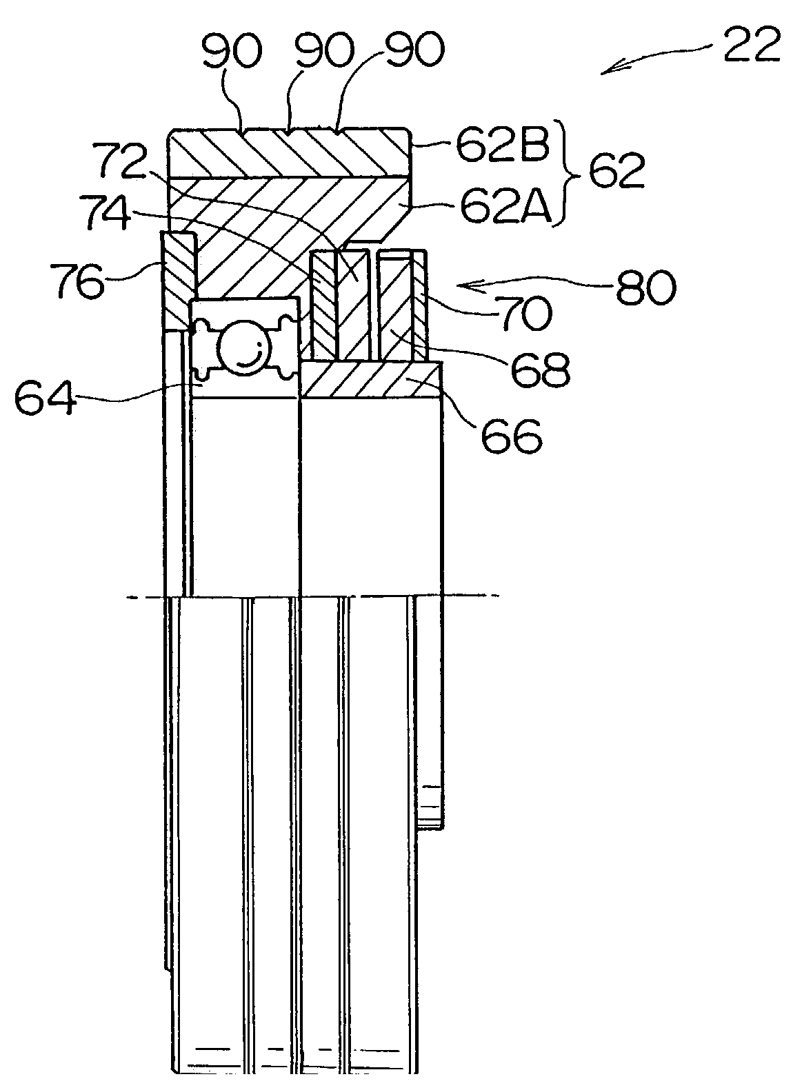
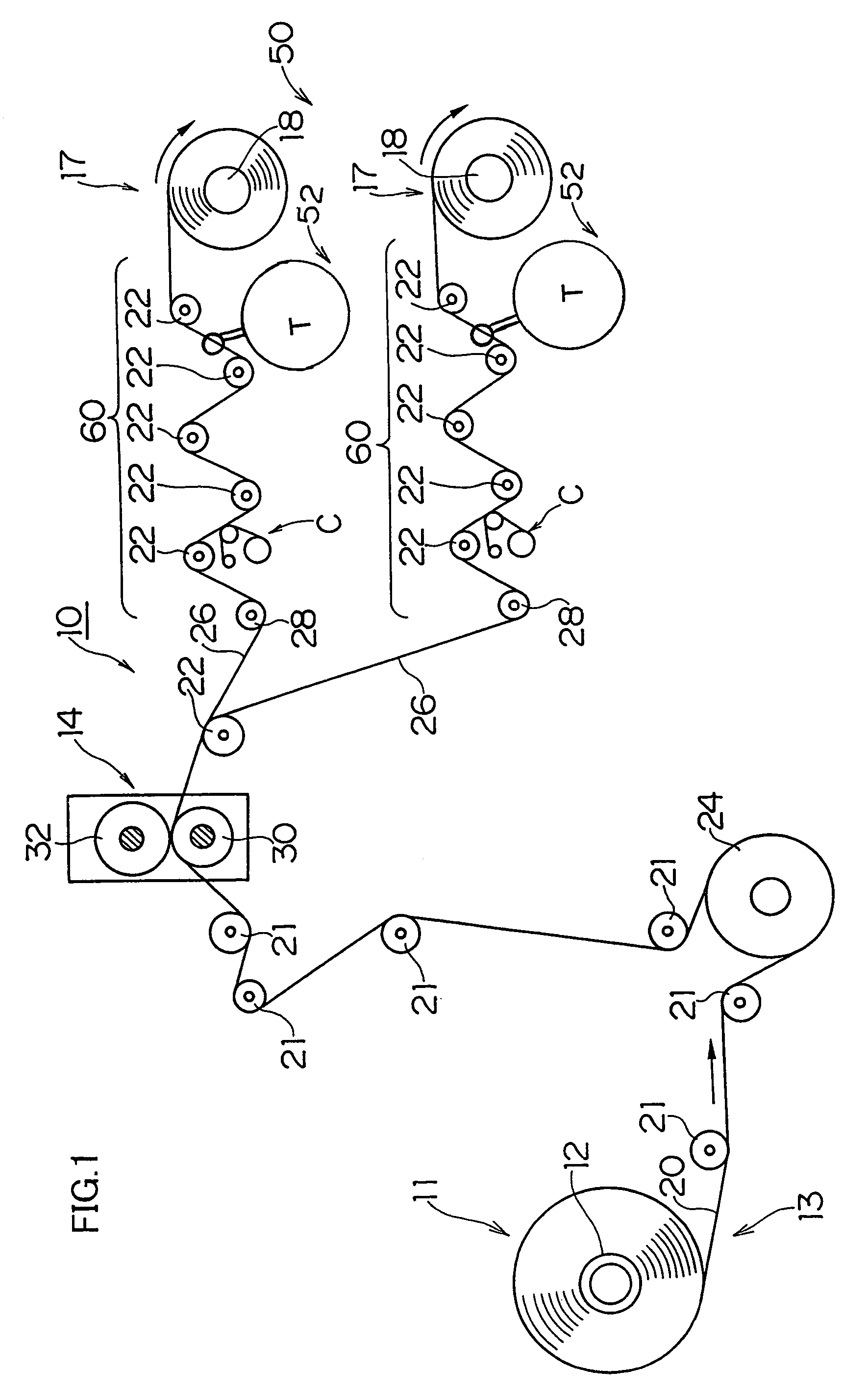
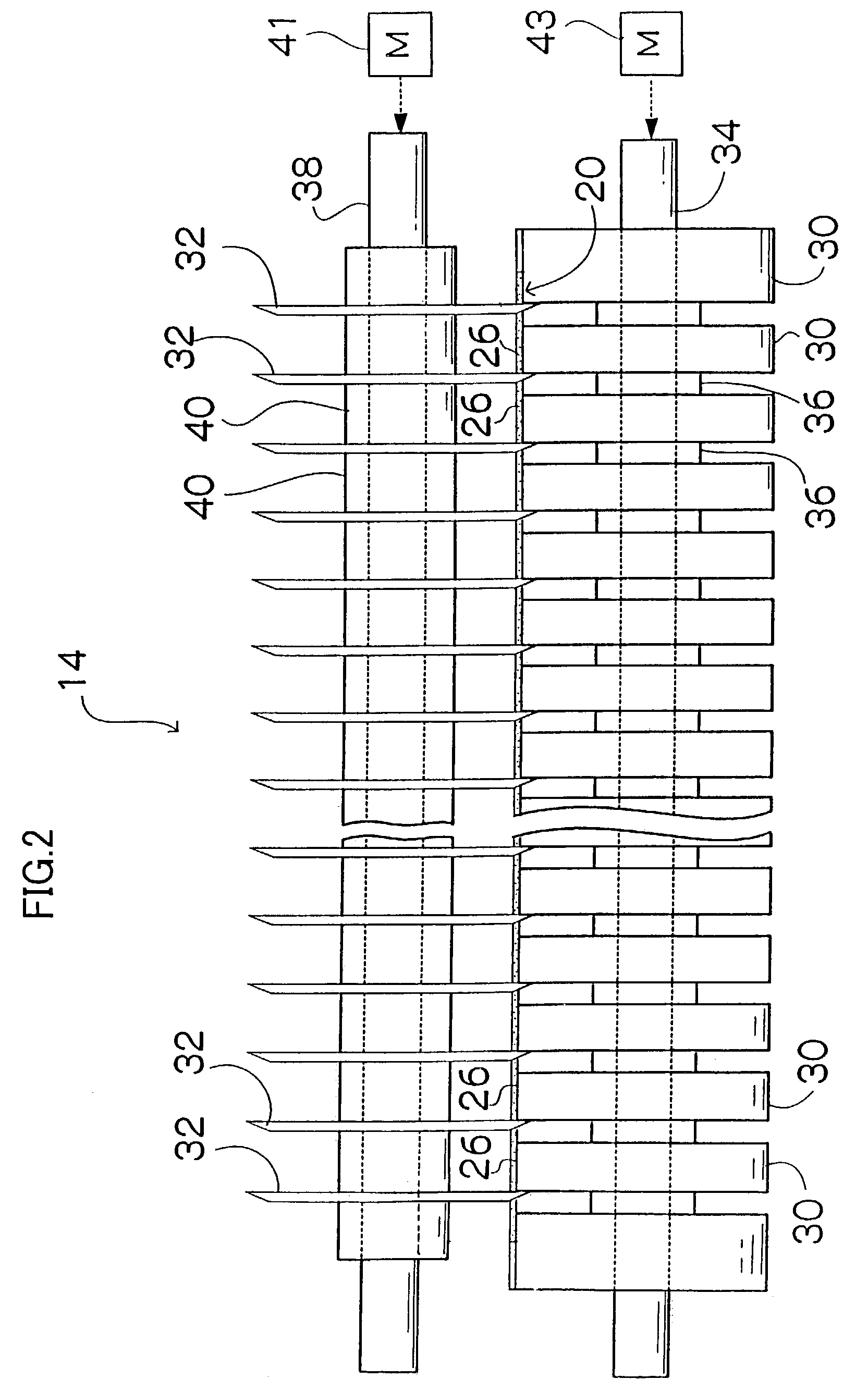
[0023]A magnetic tape manufacturing apparatus 10 according to an embodiment of the present invention, which is shown in FIG. 1 as an example, comprises a tape supply device 13, which draws out a wide web-like magnetic tape material 20 wound in roll form from the delivery side; a slitter 14, which slits the magnetic tape material 20 into a plurality of narrow magnetic tapes 26; a tape take-up device 50, which takes up the magnetic tapes 26 individually on hubs (cores) 18 of winding reels 17 on the take-up side; and a tape transporting device 60, which is provided between the slitter 14 and the tape take-up device 50 and guides the individual magnetic tapes 26 to the tape take-up device 50 while supporting the respective magnetic tapes by means of roller members 22, 22 . . . , which are guide rollers. FIG. 2 is a schema...


PUM

PropertyMeasurementUnit
widthaaaaaaaaaa
widthaaaaaaaaaa
widthaaaaaaaaaa

Abstract

The magnetic tape manufacturing apparatus draws out a wide web-like magnetic tape material wound in roll form from the delivery side, slits the magnetic tape material into a plurality of narrow magnetic tapes by use of a slitter while transporting the magnetic tape material, and winds the narrow magnetic tapes on cores on the winding side through a tape transporting device. In the tape transporting device, roller members supporting the narrow magnetic tapes are mounted on supporting shafts, respectively, and an eddy current type clutch is internally mounted on at least one of the supporting shafts so that the eddy current type clutch controls rotation of the one of supporting shafts to control tension of the narrow magnetic tape supported on the roller member mounted on the one of supporting shafts. Hence, by making the tension of the individual magnetic tapes uniform, productivity and product quality can be stabilized and improved and yield can also be improved.

Description

BACKGROUND OF THE INVENTION[0001]1. Field of the Invention[0002]The present invention relates to a method of manufacturing magnetic tape and, more particularly, to a method of manufacturing magnetic tape such as tape for computer data backup, audiotape and videotape.[0003]2. Description of the Related Art[0004]In a method of manufacturing various types of magnetic tape such as tape for computer data backup, audiotape and videotape, a wide web-like magnetic tape material wound in roll form is drawn out from the delivery side, and slit into a plurality of narrow magnetic tapes by use of a slitter while being transported, and the magnetic tapes are wound on cores on the winding side.[0005]A conventional slitter used in the manufacturing of magnetic tapes is a device that slits a wide web-like magnetic tape material into a plurality of magnetic tapes by use of pairs of upper and lower rotary blades. The rotary blades are generally constituted by a plurality of rotary blades formed as be...

Claims


Application Information

Patent Timeline
Patent Type & Authority Patents(United States)
IPC IPC(8): B65H18/08B26D7/14B26D1/24B65H18/10B65H23/188B65H23/26B65H35/02G11B5/84G11B15/43
CPCB65H18/103B65H23/26B65H35/02G11B15/43B65H2301/4148B65H2403/7241B65H2701/378B65H2220/09
Inventor ITO, HIROMICHI
Owner FUJIFILM HLDG CORP
Why Eureka
Try Eureka