Device for adjusting the armature stroke of a solenoid valve

a solenoid valve and armature stroke technology, which is applied in the direction of valve operating means/releasing devices, fuel injecting pumps, machines/engines, etc., can solve the problems of high production costs and achieve the effect of ensuring the performance of the replicable injector

Inactive Publication Date: 2006-02-07
ROBERT BOSCH GMBH
View PDF23 Cites 29 Cited by
  • Summary
  • Abstract
  • Description
  • Claims
  • Application Information

AI Technical Summary

Benefits of technology

[0009]In an advantageous feature of the invention, the magnet or magnet assembly, which may comprise an electromagnet assembly with coils, may be disposed essentially around the stop bush, but it is also possible for the magnet or corresponding magnet assembly to be disposed essentially in the stop bush. “Essentially” should be understood here to mean that the magnet does not entirely surround the corresponding stop bush, or that the corresponding magnet is not entirely surrounded by the stop bush. By this kind of disposition of the magnets and stop bush, on the one hand especially good accessibility to the stop bush exists, depending on given conditions, and on the other, a space-saving design of the device or electromagnetic valve of the invention that suits the most various installation conditions can be attained, which in turn can lead to savings of material and thus to a reduction in production costs.
[0017]The electromagnetic valve of the invention having the characteristics of claim 10, which is intended in particular for use in a fuel injector, has a magnet or magnet assembly and an armature, and also has a device for adjusting an armature stroke of the armature upon actuation of the magnet, having a stop bush is disposed relative to a main body of the electromagnetic valve or of the injector in an axial guide and is adjustable in its axial position relative to the main body, wherein this stop bush forms a stop for limiting the armature stroke in an axial direction, and wherein the device for adjusting the armature stroke has an variable adjusting element with two threaded portions of different thread pitch (P) and the same thread direction, by which element the position of the stop bush is adjustable, and the first threaded portion engages a corresponding first threaded portion of the stop bush, and the second threaded portion engages a corresponding second threaded portion of the main body. Because of the adjustability—even retroactively—of the axial position of the stop bush by a suitable adjusting element, economical production of a corresponding electromagnetic valve is possible, and in particular in the use of an electromagnetic valve of this kind, because of the resultant possibility of close-tolerance armature stroke adjustment, replicable injector performance is assured.

Problems solved by technology

This process leads to high costs in production.

Method used


Image

  • Device for adjusting the armature stroke of a solenoid valve
  • Device for adjusting the armature stroke of a solenoid valve
  • Device for adjusting the armature stroke of a solenoid valve

Examples


Embodiment Construction

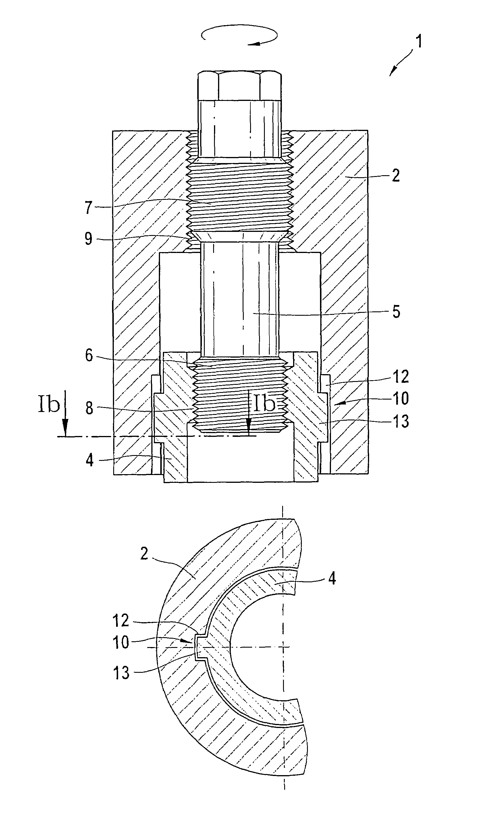
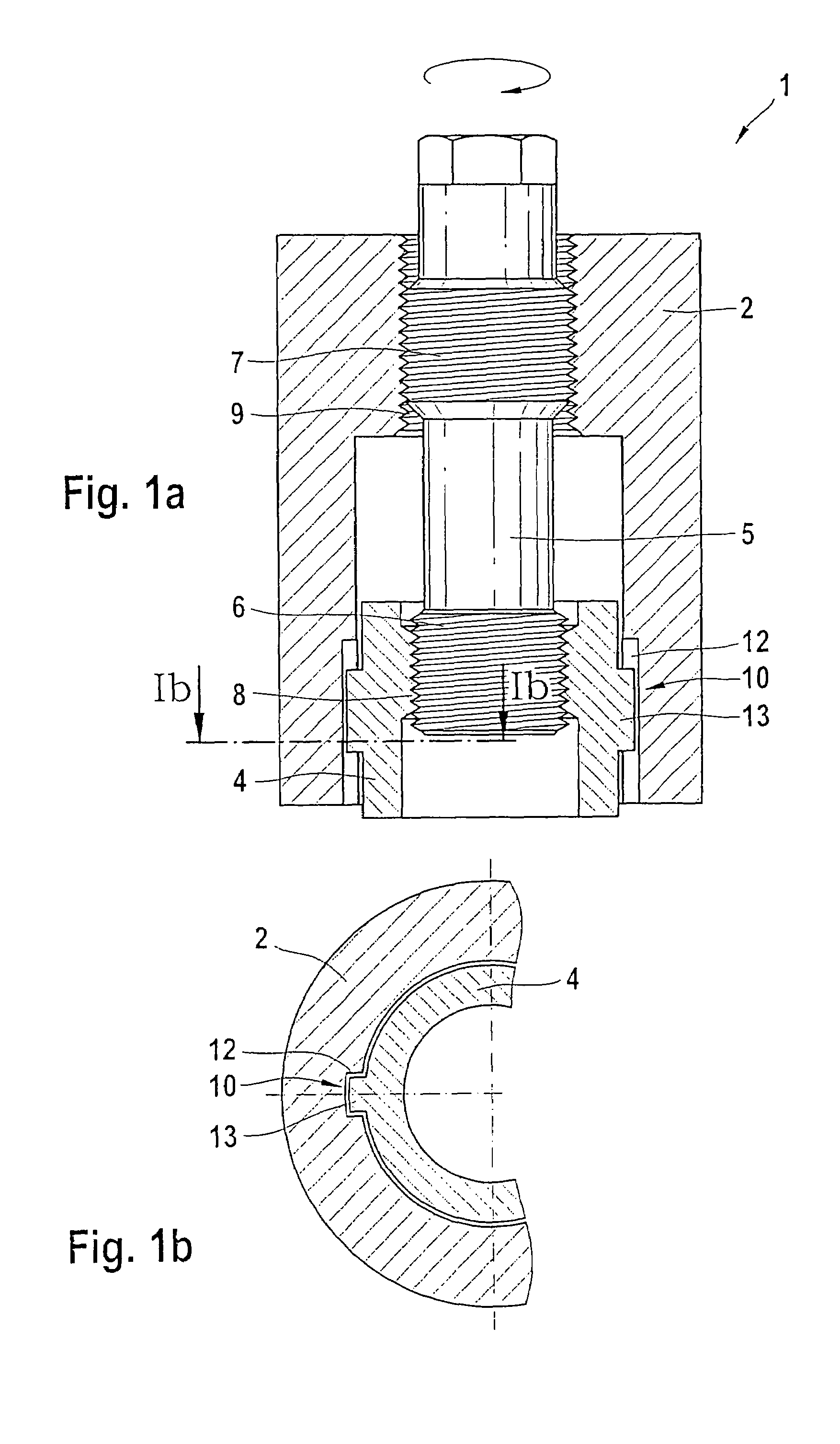
[0027]FIG. 1, in a fragmentary sectional view, is a schematic illustration of the device according to the invention for adjusting an armature stroke of an armature of an electromagnetic valve.

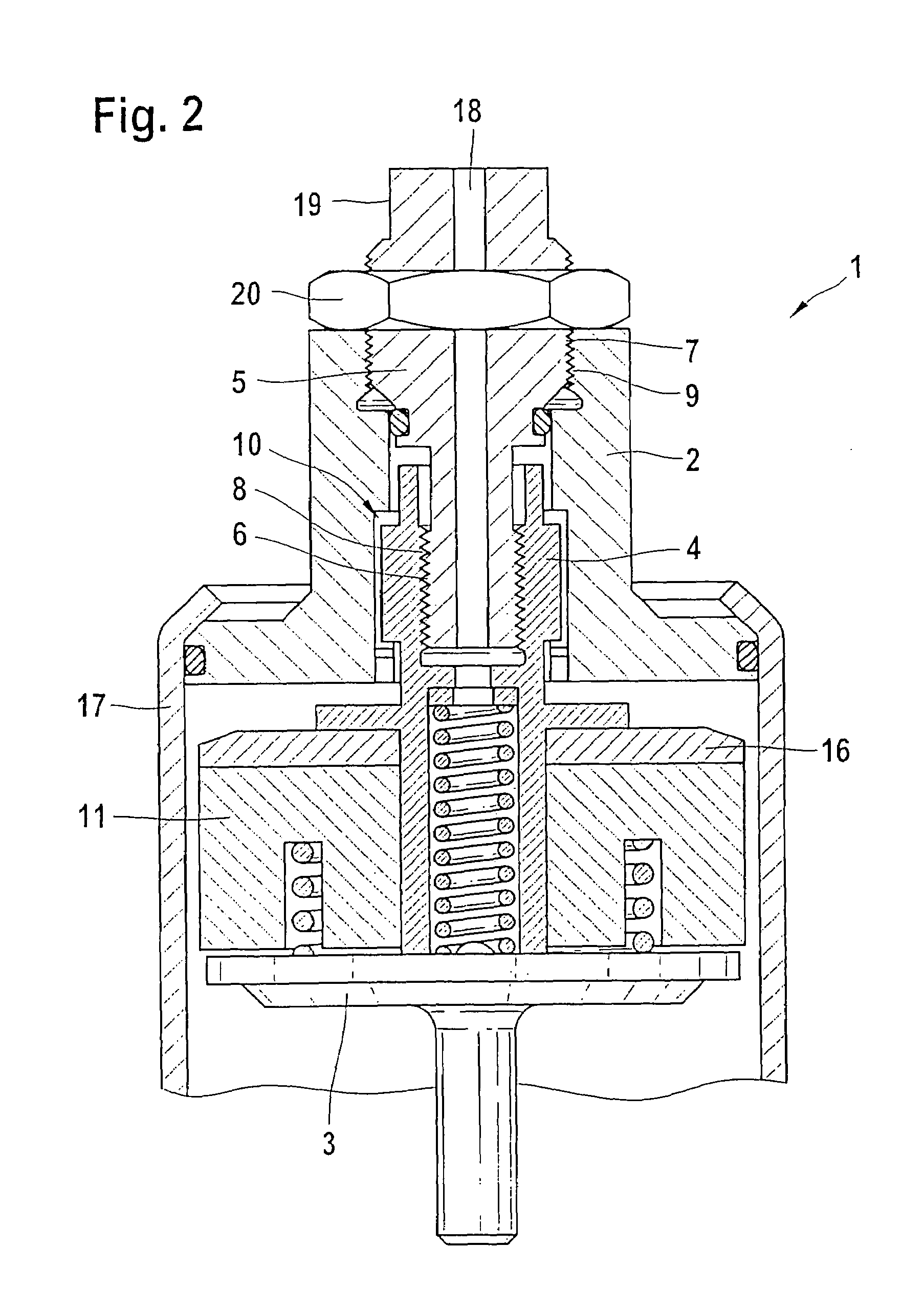
[0028]In a main body 2, which is part of an electromagnetic valve 1, a stop bush 4 is disposed in such a way that by means of an axial guide 10 it is guided movably in the main body 2. The axial guide 10 is formed by two recesses 12 in the main body 2 and two corresponding protrusions 13 of the stop bush 4 which are received in these recesses. The stop bush 4, in an inner region thereof, has a first threaded portion 8 which is designed as a female thread. The main body 2, in its upper portion, has a second threaded portion 9 which is embodied as a female thread. An adjusting element 5 is disposed in both the main body 2 and stop bush 4 and rotatably engages these elements with a first threaded portion 6 and a second threaded portion 7, respectively, in the respective first threaded portion 8 of...


PUM


Abstract

A device for adjusting an armature stroke of an armature upon actuation of a magnet of an electromagnetic valve having a stop bush disposed in an axial guide relative to a main body of the electromagnetic valve and adjustable in its axial position relative to the main body of the electromagnetic valve, which stop bush forms a stop for limiting the armature stroke in an axial direction. A variable adjusting element with two threaded portions providing a variable thread pitch (P) and the same thread direction by which the position of the stop bush is adjustable. The first threaded portion engages a corresponding first threaded portion of the stop bush, and the second threaded portion engages a corresponding second threaded portion of the main body, and to an electromagnetic valve having a corresponding device, in particular for use in a fuel injector.

Description

CROSS-REFERENCE TO RELATED APPLICATIONS[0001]This application is a 35 USC 371 application of PCT / DE 03 / 02128 filed on Jun. 26, 2003.BACKGROUND OF THE INVENTION[0002]1. Field of the Invention[0003]For supplying fuel to combustion chambers of internal combustion engines, injection systems for injecting fuel are used whose injectors are exposed to extremely high pressures. In order not to impair the efficiency of such fuel injectors, it is absolutely necessary to assure replicable injector performance. Suitable injectors as a rule have an electromagnetic valve, and an armature stroke of such an electromagnetic valve must be adjusted precisely when applicable injectors are being installed, since the injector dynamics are definitively affected by the armature stroke. For instance, given a fixed triggering duration of a magnet coil of the electromagnetic valve, the injected fuel quantity is dependent on the armature stroke.[0004]2. Description of the Prior Art[0005]In currently known elec...

Claims


Application Information

Patent Timeline
Patent Type & Authority Patents(United States)
IPC IPC(8): F16K31/06F02M51/06F02M59/46F02M61/16F02M63/00
CPCF02M63/0015F02M61/168F02M51/0642F02M61/161F02M2200/8076F02M2200/507
Inventor PAUER, THOMASMIEHLE, TILMANLALIC, HRVOJE
Owner ROBERT BOSCH GMBH
Why Eureka
Try Eureka