Method and device for controlling the braking equipment of a motor vehicle

a technology for braking equipment and motor vehicles, which is applied in the direction of brake action initiation, braking systems, transportation and packaging, etc., can solve the problems of unsuitable parts for use in “, insufficient fixed predetermined braking force for holding the motor vehicle, and unwanted or uncontrollable traveling states

Inactive Publication Date: 2006-02-07
LUCAS AUTOMOTIVE GMBH
View PDF21 Cites 17 Cited by
  • Summary
  • Abstract
  • Description
  • Claims
  • Application Information

AI Technical Summary

Benefits of technology

[0020]An object of the present invention is to provide a method and a device for controlling braking equipment of a motor vehicle, which assist the vehicle driver in a “stop-and-go” operation and to make this more comfortable, while avoiding the above-mentioned disadvantages of the state of the art.
[0023]The present invention also provides a method for controlling braking equipment of a motor vehicle, wherein an operating state of a motor vehicle is detected, in which the motor vehicle is to be brought from a state of standstill, in which the traveling speed of the motor vehicle is zero, into a traveling state. If such an operating state is present, braking equipment of the motor vehicle is controlled such that the braking forces produced by the braking equipment in the state of standstill are reduced in such a way as to allow a transition into the traveling state. Here too, the controlled actuation, to be more precise the controlled de-activation, of the braking equipment takes place without any actuation by the vehicle driver, which reduces the braking force.
[0024]In order to allow a transition in the traveling state jerk-free as much as possible and to avoid increased loads or damages of the braking equipment, in particular of brake linings, when reducing the braking forces during a starting event, the respective operation state of the motor vehicle can be controlled during reduction of the braking forces. Here, in particular, it is contemplated to reduce, at least for a short period of time, the rotational engine speed and / or the motor torque of the motor vehicle when starting and during a reduction of braking forces occurring along therewith. In particular in case of a powerful acceleration events (racing start), in this manner, the reduction of braking forces and the building up of driving power acting on the wheels can be coordinated with respect to each other. Independence of the reduction of the braking forces, the engine speed and / or the motor torque can be brought to a value desired and predefined, respectively, by the vehicle driverjump-wise, step-wise, linearily or according to a different function in order to enable the desired starting event.

Problems solved by technology

The devices described above have disadvantages, which is why they are in particular unsuitable for use in a “stop-and-go” operation or do not represent any assistance for a vehicle driver.
This means that, for example, the fixedly predetermined braking force may be insufficient for holding the motor vehicle at a standstill when it is on a slope.
The holding brake is consequently also activated during traveling operation of the motor vehicle, so that unwanted or uncontrollable traveling states may occur, especially at high speeds.
This type of actuation of the holding brake also increases wear as the holding brake does not, as intended, just provide braking forces when the motor vehicle is at a standstill.
Therefore, there it is not possible to let the motor vehicle roll when the accelerator pedal is not actuated, which is desirable in particular where a “stop-and-go” operation is concerned, as braking forces are always automatically produced in this case.
As long as the vehicle is still moving, the brake system described therein operates in a conventional manner and consequently does not assist the vehicle driver in a “stop-and-go” operation.

Method used


Image

  • Method and device for controlling the braking equipment of a motor vehicle
  • Method and device for controlling the braking equipment of a motor vehicle
  • Method and device for controlling the braking equipment of a motor vehicle

Examples


Embodiment Construction

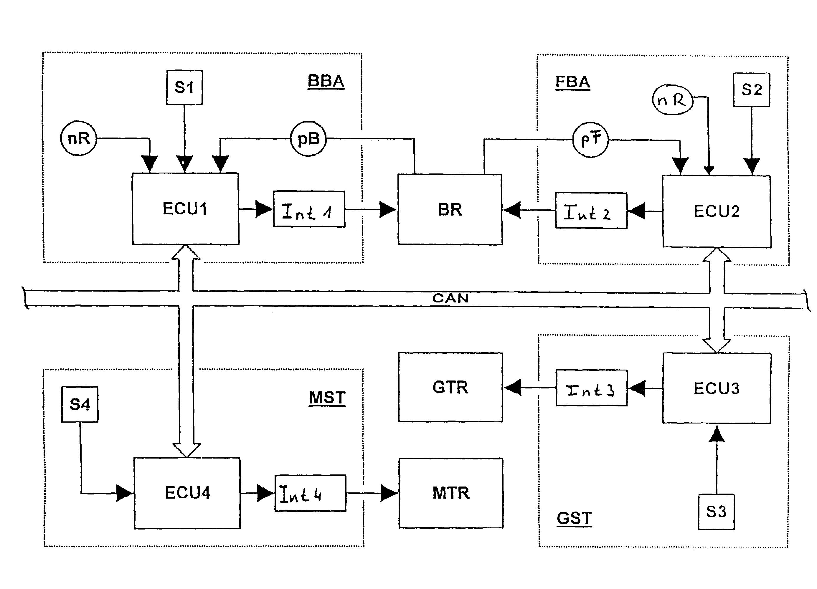
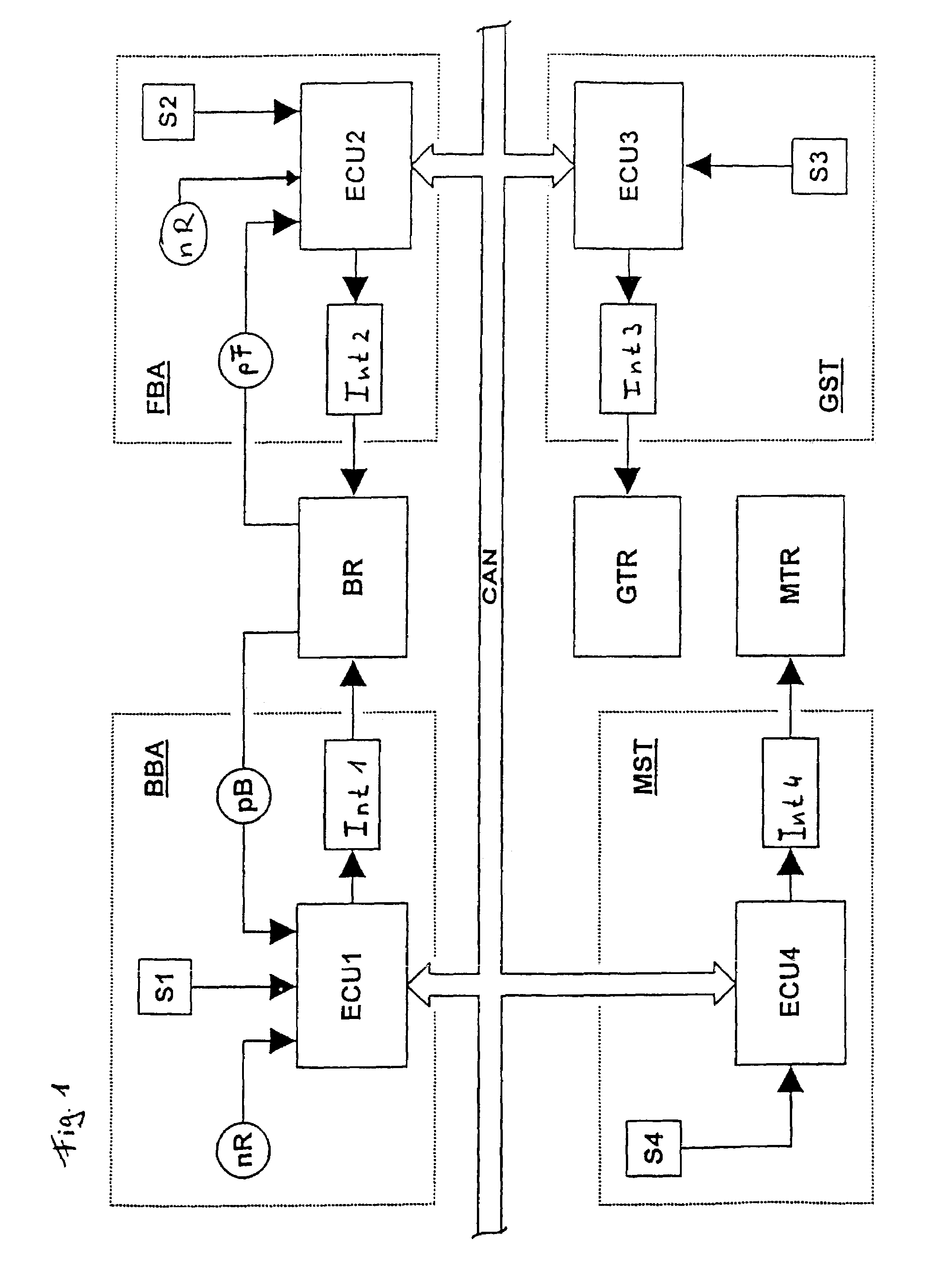
[0043]According to FIG. 1, braking equipment of a motor vehicle, which is not shown, comprises a controllable service brake system BBA and a controllable holding brake system FBA, which together or individually actuate brakes BR of the motor vehicle. A transmission control GST for a transmission GTR and an engine control MST for an engine MTR as further vehicle equipment (vehicle components), can be also seen in FIG. 1.

[0044]The service brake system BBA comprises a control unit ECU1, a sensor means S1 and sensors nR and bP. The control unit ECU1 serves to control the service brake system BBA using signals from the sensor means S1 and the sensors nR and pB. Quantities / parameters, which indicate an operation of the service brake system desired by a vehicle driver, are detected by the sensor means S1. Depending on the respective application, the sensor means S1 detects positions and / or movements of a brake pedal (not shown), positions of a brake light switch, positions and / or movements...


PUM


Abstract

The present invention relates to a method and a device for controlling braking equipment of a motor vehicle. Here, an operating state of a motor vehicle is determined, in which the motor vehicle is to be brought from a state, in which its speed is not zero, into a state, in which the vehicle no longer moves. If such a transition from a traveling state into a state of standstill is determined, braking equipment of the motor vehicle is controlled such that braking forces are produced, which are capable of bringing the motor vehicle into the state of standstill and / or assisting a vehicle driver in doing this. It is also possible to produce braking forces in the state of standstill, which are capable of holding the motor vehicle in the state of standstill. The present invention additionally enables to assist a vehicle driver when starting a motor vehicle. In this case, an operating state of the motor vehicle is detected in which the motor vehicle is to be brought from a state of standstill into a traveling state. If such an operating state is present, the braking equipment of the motor vehicle is controlled such that the braking forces produced by the braking equipment in the state of standstill are reduced in such a way as to allow a transition into the traveling state and / or to assist the vehicle driver in this respect.

Description

CROSS REFERENCE TO RELATED APPLICATIONS[0001]This application is a continuation of International Application No. PCT / EP01 / 14944 filed Dec. 18, 2001, the disclosures of which are incorporated herein by reference, and which claimed priority to German Patent Application No. 100 63 062.6 filed Dec. 18, 2000, the disclosures of which are incorporated herein by reference.[0002]The present invention relates to a method and a device for controlling braking equipment of a motor vehicle. The present invention relates in particular to a method and a device for controlling braking equipment during a so-called “stop-and-go” operation of a motor vehicle, in which successive operating states alternate with braking, parked and starting phases.BACKGROUND OF THE INVENTION[0003]According to the Kraftfahrttechnisches Taschenbuch, Robert Bosch GmbH, 20th edition, page 502 ff., the term “braking equipment” is understood to mean all brake systems of a motor vehicle for the purpose of reducing its speed, b...

Claims


Application Information

Patent Timeline
Patent Type & Authority Patents(United States)
IPC IPC(8): B60T8/32B60T7/12B60T8/58B60T13/66B60W10/04B60W10/18B60W30/18
CPCB60T7/122B60W30/18027B60W10/18B60W10/04B60K2741/205B60W30/1819
Inventor KINDER, RALFKLAPPER, GERHARDSHOKOUFANDEH, REZAENDRES, FRANZ-JOSEFLEITER, RALFMAACK, LORENZSONS, ANDREAS
Owner LUCAS AUTOMOTIVE GMBH
Why Eureka
Try Eureka