Method for forming images and intermediate transfer recording medium

a technology of intermediate transfer and recording medium, which is applied in the direction of lithography, instruments, transportation and packaging, etc., can solve the problems of image damage, lightfastness and weathering resistance, when exposed to service conditions severe in terms of various fastness properties, and achieve excellent various fastness properties

Inactive Publication Date: 2006-02-07
DAI NIPPON PRINTING CO LTD
View PDF9 Cites 21 Cited by
  • Summary
  • Abstract
  • Description
  • Claims
  • Application Information

AI Technical Summary

Benefits of technology

[0010]Accordingly, it is an object of the present invention to solve the above problem of the prior art and to provide a method for image formation, which can yield a thermally transferred image having excellent various fastness properties even under severe service conditions, and an intermediate transfer recording medium for use in the method for image formation.
[0020]Thus, the transferred portion with the thermally transferred image formed thereon is provided on the object, and the transferred portion as the outermost surface in the final form of the print is superimposed once or more on the transferred portion with the thermally transferred image formed thereon. By virtue of this, a strong film for protecting the thermally transferred image can be provided, and, even when the print is exposed to severe service conditions, the thermally transferred image has excellent various fastness properties.

Problems solved by technology

The formation of an image on an object using the conventional intermediate transfer recording medium, however, poses a problem that the image face in the transfer portion of the intermediate transfer recording medium comes into contact with the object and thus, although a film is formed on the outermost surface of the image on the object, the image, when exposed to service conditions which are severe in terms of various fastness properties, particularly chemical resistance, lightfastness and weathering resistance, is damaged.

Method used


Image

  • Method for forming images and intermediate transfer recording medium
  • Method for forming images and intermediate transfer recording medium
  • Method for forming images and intermediate transfer recording medium

Examples


example 1

[0061]A 12 μm-thick transparent polyethylene terephthalate film was first provided as a substrate film. The following coating liquid for a peel layer was coated on the surface of the substrate film, and the coating was dried to form a 1.5 μm-thick peel layer on the substrate film.

[0062]

(Coating liquid for peel layer)Acrylic resin40 partsPolyester resin 2 partsMethyl ethyl ketone50 partsToluene50 parts

[0063]An ultraviolet-curable acrylic resin (“Yupimer LZ 065 S,” manufactured by Mitsubishi Chemical Corporation) was then coated onto the peel layer by gravure reverse coating. The coating was exposed to ultraviolet light and was dried to form a 2.0 μm-thick hologram layer. A hologram pattern was formed in the hologram layer by providing an original plate having a concave / convex pattern of interference fringes of a hologram and forming fine concaves and convexes by embossing.

[0064]Further, a 500 angstrom-thick titanium oxide layer was vacuum deposited as a transparent vapor deposited la...

example 2

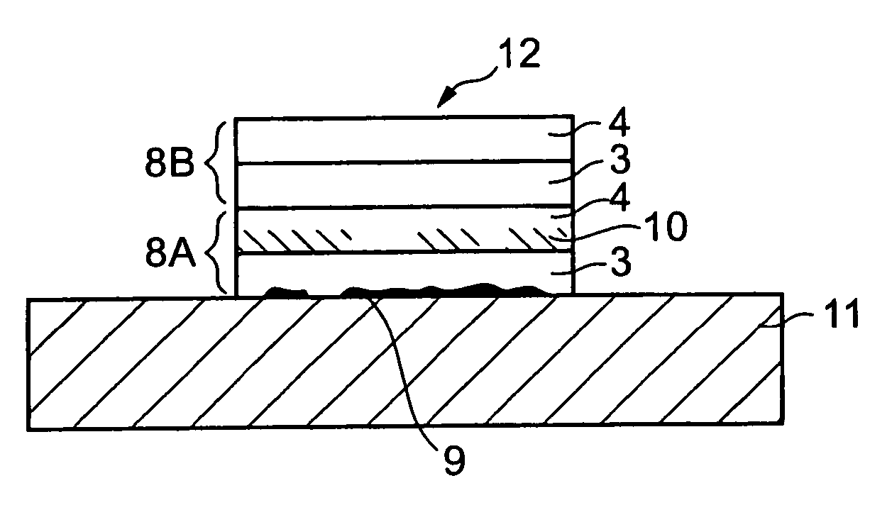
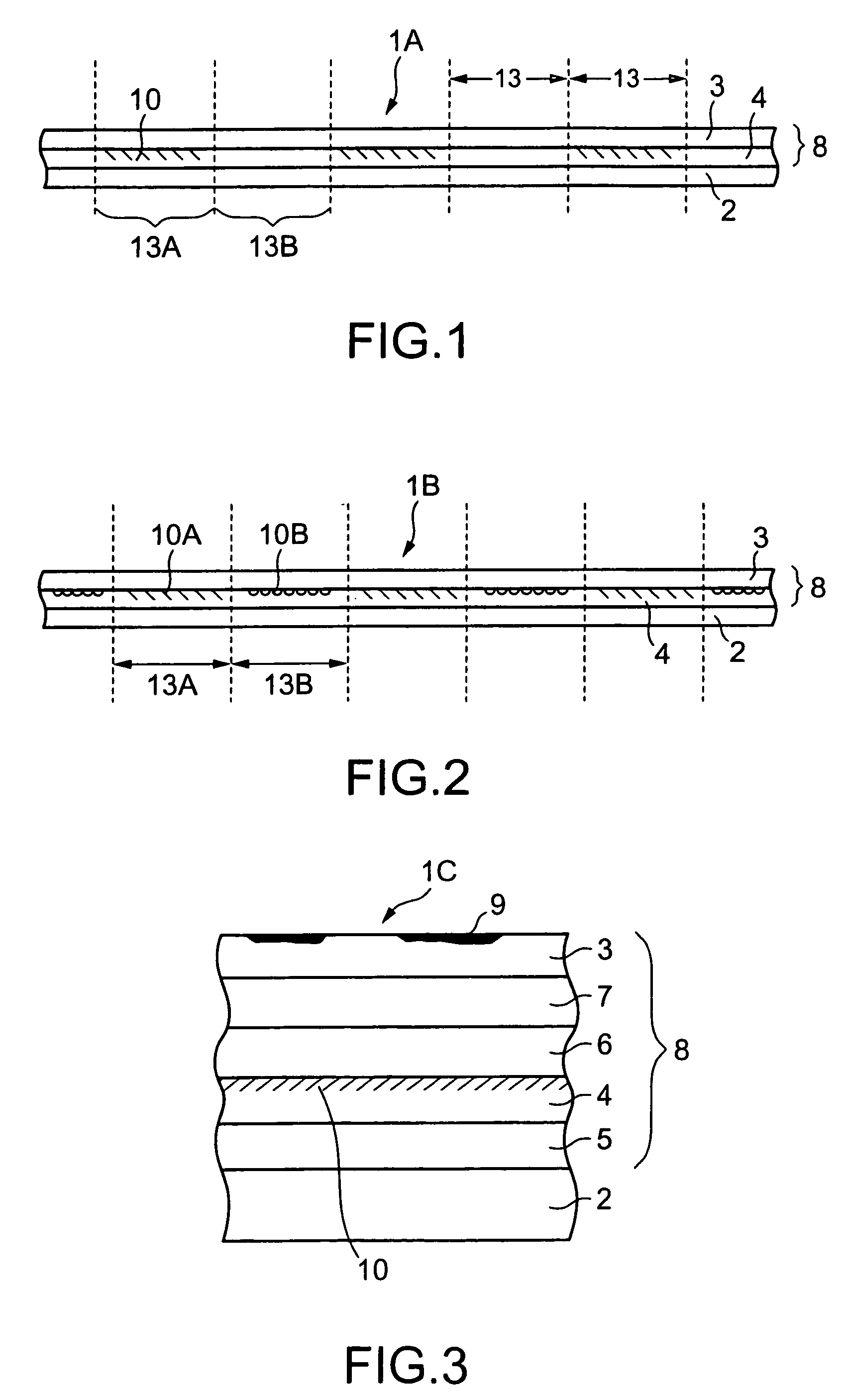
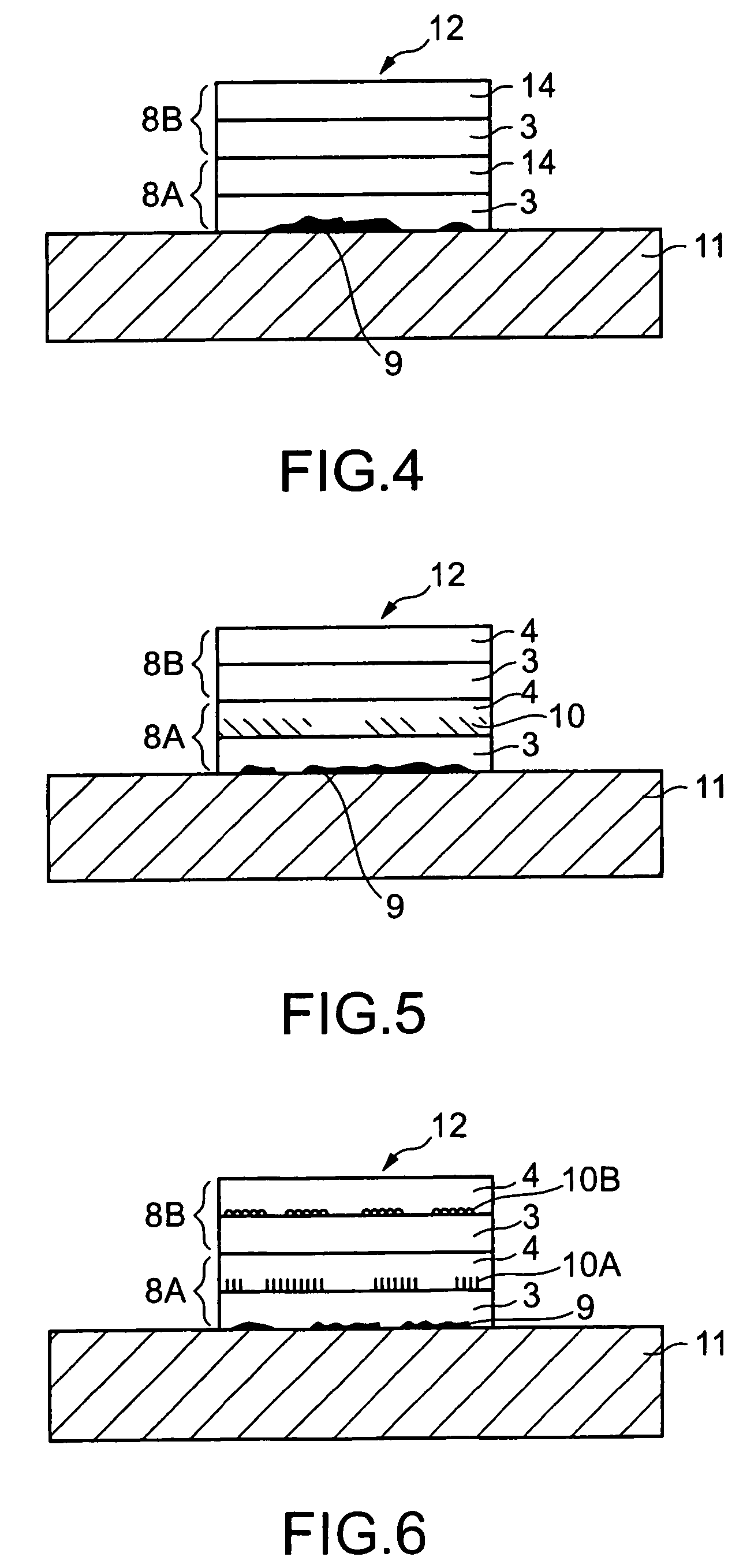
[0071]A peel layer, a hologram layer, a transparent vapor deposited layer, and a receptive layer were provided in that order on a substrate film in the same manner as in Example 1, except that the hologram image was formed as shown in FIG. 2, that is, two types of hologram images 10A and 10B were alternately and repeatedly provided in the transfer portions in the intermediate transfer recording medium as counted on the assumption that one image is set in one image plane.

[0072]Thus, an intermediate transfer recording medium of Example 2 was prepared.

[0073]An image was thermally transferred, on a receptive layer (image plane portion 13A) in the intermediate transfer recording medium, using a thermal transfer sheet comprising colorant layers of yellow, magenta, and cyan provided in a face serial manner.

[0074]Thereafter, a transfer portion 8A with the above image formed thereon was transferred onto a passport (an object) at its predetermined position.

[0075]Next, the intermediate transfe...


PUM

PropertyMeasurementUnit
thicknessaaaaaaaaaa
thicknessaaaaaaaaaa
thicknessaaaaaaaaaa

Abstract

The present invention provides a method for image formation, that can yield thermally transferred images which are excellent in various fastness properties even under severe service conditions, and an intermediate transfer recording medium for use in the method for image formation. The method for image formation comprises the steps of: providing an intermediate transfer recording medium comprising a substrate film and a transfer portion provided separably on the substrate film; forming an image on the intermediate transfer recording medium in its transfer portion; transferring the transfer portion onto an object; and, thereafter, again transferring the intermediate transfer recording medium in its next transfer portion once or more onto the object with the image formed thereon. In this case, in the intermediate transfer recording medium, a hologram image is set every at least second image plane, and an image can be formed on the transfer portion having the hologram image. This can offer an advantage that the transfer portion, with a thermally transferable image formed thereon, can be transferred onto an object followed by the superimposition of a transfer portion, to be served as the outermost surface in the final form onto the transferred portion once or more to provide a strong film for protecting the thermally transferred image. Thus, the problems of the prior art could have been solved.

Description

TECHNICAL FIELD[0001]The present invention relates to a method for image formation which can yield a thermally transferred image possessing excellent various fastness properties even under severe service conditions, and an intermediate transfer recording medium for use in the method for image formation.BACKGROUND ART[0002]Thermal transfer has become extensively used as a simple printing method. The thermal transfer is a method which comprises the steps of: putting a thermal transfer sheet, comprising a colorant layer provided on one side of a substrate sheet, on top of a thermal transfer image-receiving sheet optionally provided with an image-receptive layer; and image-wise heating the backside of the thermal transfer sheet by heating means such as a thermal head to selectively transfer the colorant contained in the colorant layer to form an image on the thermal transfer image-receiving sheet.[0003]Thermal transfer methods are classified into thermal ink transfer (hot melt-type ther...

Claims


Application Information

Patent Timeline
Patent Type & Authority Patents(United States)
IPC IPC(8): B44C1/165B41F1/16B41M5/382B42D15/10B41M5/50B41M5/52B41M7/00B44C1/00B44C1/17G03H1/02G03H1/18
CPCB41M5/0256B41M5/38257B41M7/0027B44C1/1716B41M7/0045B44C1/1725Y10T428/1405G03H2250/10Y10T428/24802
Inventor OSHIMA, KATSUYUKIODAMURA, KOZOIMAI, TAKAYUKIISHIDA, TADAHIROTAKASAKI, ETSUO
Owner DAI NIPPON PRINTING CO LTD
Why Eureka
Try Eureka