Analyte measurement kit

a technology of analyte and kit, which is applied in the field of medical diagnostic devices, can solve the problems of inaccurate measurement reading, inconvenient measurement, and inability to precisely prevent linear or longitudinal movement along the y-axis in the configuration of the v-notch, and achieve the effect of facilitating the measurement of the analyte targeted

Inactive Publication Date: 2006-02-07
LIFESCAN IP HLDG LLC
View PDF13 Cites 111 Cited by
  • Summary
  • Abstract
  • Description
  • Claims
  • Application Information

AI Technical Summary

Benefits of technology

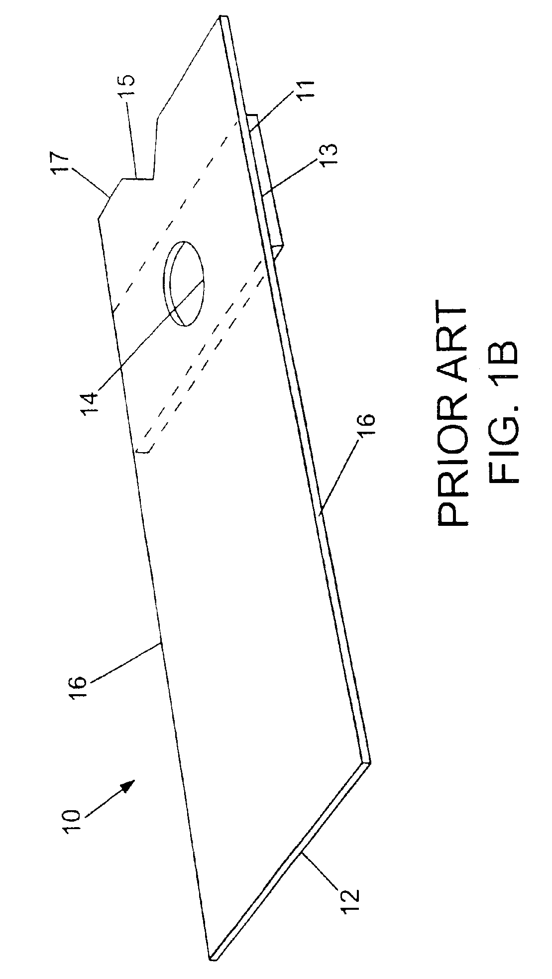
[0014]The subject test devices may include a support member and a sample-absorbing member. The above-mentioned notch and aperture of the test devices are features of the support member. Affixed to the bottom surface of the support member is a sample-absorbing member in the form of a pad which covers the aperture. The pad is made of a hydrophilic material and, as such, absorbs the fluid sample deposited on the aperture. A reagent material may be contained within the pad for facilitating the measurement of the analyte targeted for measurement.

Problems solved by technology

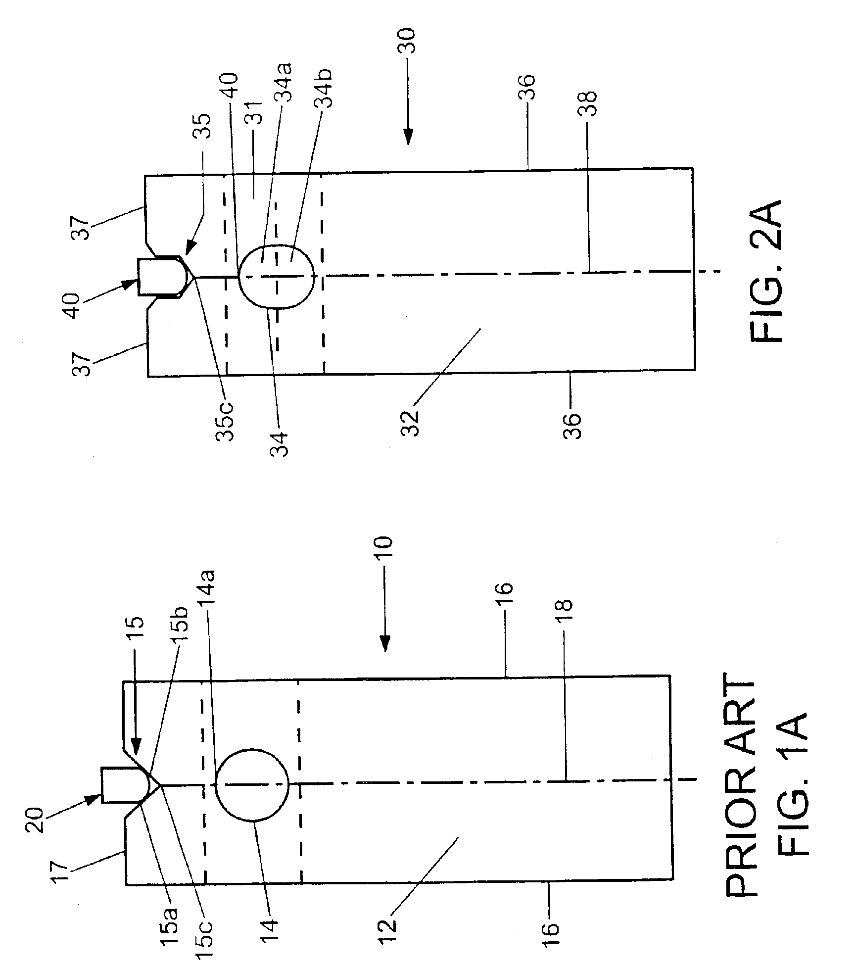
This is intended to align aperture 14 over the light source within the measurement meter; however, it is this movement or lateral “play,” i.e., side-to-side shifting, of test strip 10 that is often the cause of an improperly aligned test strip.
Additionally, the V notch configuration has no means for specifically preventing linear or longitudinal movement along the y-axis 18 of test strip 10 once it is positioned within the test strip holder.
Nonetheless, upon rebound, aperture 14 may be displaced enough such that none or an insufficient amount of its interior surface area and the sampled fluid are aligned with the light source, resulting in an inaccurate measurement reading.
Such proximal displacement of the test strip, and of the measurement aperture, is such that the aperture's exposure, and thus the sampled fluid's exposure, to the light source beam of the meter is insufficient to provide an accurate measurement reading of the sample deposited within the aperture.

Method used


Image

  • Analyte measurement kit
  • Analyte measurement kit
  • Analyte measurement kit

Examples


Embodiment Construction

[0020]Before the present invention is described in further detail, it is to be understood that this invention is not limited to the particular embodiment described, as such may, of course, vary. It is also to be understood that the terminology used herein is for the purpose of describing particular embodiments only, and is not intended to be limiting, since the scope of the present invention will be limited only by the appended claims.

[0021]Where a range of values is provided, it is understood that each intervening value, to the tenth of the unit of the lower limit unless the context clearly dictates otherwise, between the upper and lower limit of that range and any other stated or intervening value in that stated range is encompassed within the invention. The upper and lower limits of these smaller ranges may independently be included in the smaller ranges is also encompassed within the invention, subject to any specifically excluded limit in the stated range. Where the stated rang...


PUM

PropertyMeasurementUnit
widthaaaaaaaaaa
widthaaaaaaaaaa
diameteraaaaaaaaaa

Abstract

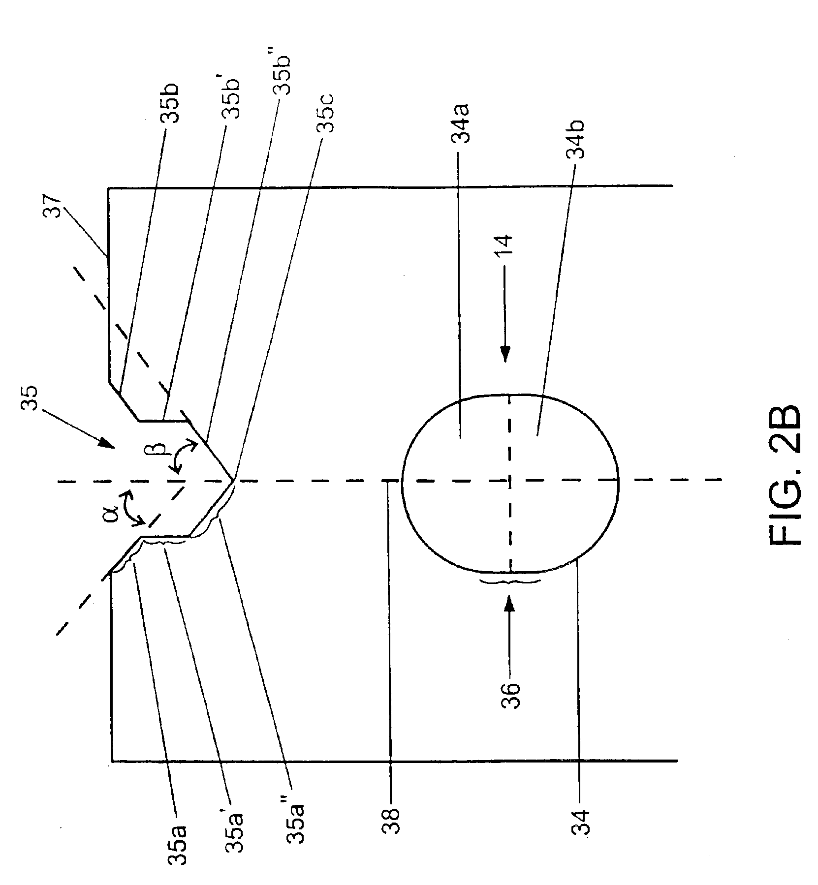
Devices, systems, methods and kits are provided for use in determining the concentration of chemical and biochemical components in aqueous fluids. The subject devices include test strips which define a longitudinal axis and include a distal edge configured for insertion into a measurement instrument and having an alignment notch formed in the distal edge for engagement with an alignment member of the measurement instrument. The alignment notch has opposing edges wherein at least a portion of the opposing edges is in substantially parallel relation to the longitudinal axis. In using the subject devices, the devices are inserted into a measurement instrument having an alignment pin. When operatively engaged with the alignment pin, the notch serves to maintain the device in a substantially motionless position. The invention is useful in a variety of applications, particularly in the determination of blood glucose concentrations.

Description

[0001]This Application is a Divisional of Ser. No. 09 / 884,368 filed Jun. 19, 2001 now U.S. Pat. No. 6,576,416, which is incorporated herein by reference in its entirety, and to which priority is claimed.FIELD OF THE INVENTION[0002]The present invention is related to the field of medical diagnostic devices for determining the concentration of chemical and biochemical components (analytes) in aqueous fluids. Particularly, the present invention is directed to measuring the concentration of an analyte in, or a property of, a biological fluid such as blood and more particularly glucose in blood.BACKGROUND OF THE INVENTION[0003]The quantification or assay of chemical and / or biochemical constituents within biological fluids, such as blood, urine, and saliva, and within biological fluid fractions or derivatives such as blood serum and blood plasma, is of ever increasing importance for medical diagnosis and treatment, as well as the quantification of exposure to therapeutic drugs, intoxicant...

Claims


Application Information

Patent Timeline
Patent Type & Authority Patents(United States)
IPC IPC(8): G01N21/00G01N33/66G01N1/00G01N33/48G01N33/487G01N33/50G01N33/558
CPCG01N33/558Y10T436/144444Y10S435/975G01N33/487G01N33/66
Inventor HAVILAND, ALANHUFFORD, WILLIAMBENNETT, GREGORYBIRD, DENNIS
Owner LIFESCAN IP HLDG LLC
Why Eureka
Try Eureka