Electromagnetic relay

a technology of electromagnetic relays and relays, applied in the field of electromagnetic relays, can solve the problems of inability to manufacture electromagnetic relays with a greatly reduced length, limit the length reduction of electromagnetic relays, etc., and achieve the effect of shortening the length and high insulating characteristics

Active Publication Date: 2006-02-07
ORMON CORP
View PDF6 Cites 15 Cited by
  • Summary
  • Abstract
  • Description
  • Claims
  • Application Information

AI Technical Summary

Benefits of technology

[0006]According to one or more embodiments of the electromagnetic relay of the invention, since the second coil terminal is disposed below the electromagnet block, a space for disposing two coil terminals side by side in the same plane as in the related-art electromagnetic relay is not needed. As one of the coil terminals does not protrude outward, the electromagnetic relay of the invention is shorter in length than the related-art electromagnetic relay. Moreover, by disposing the second coil terminal below the electromagnet block, a required insulation distance between the first and second coil terminals can be easily secured. Thus, the electromagnetic relay of the invention has high insulating characteristics.

Problems solved by technology

Therefore, there is a limitation to the reduction of the length of the above electromagnetic relay, and thus an electromagnetic relay having greatly decreased length cannot be manufactured.

Method used


Image

  • Electromagnetic relay
  • Electromagnetic relay
  • Electromagnetic relay

Examples


Embodiment Construction

[0021]Preferred embodiments according to the invention are herein after described with reference to the appended drawings of FIGS. 1 through 13.

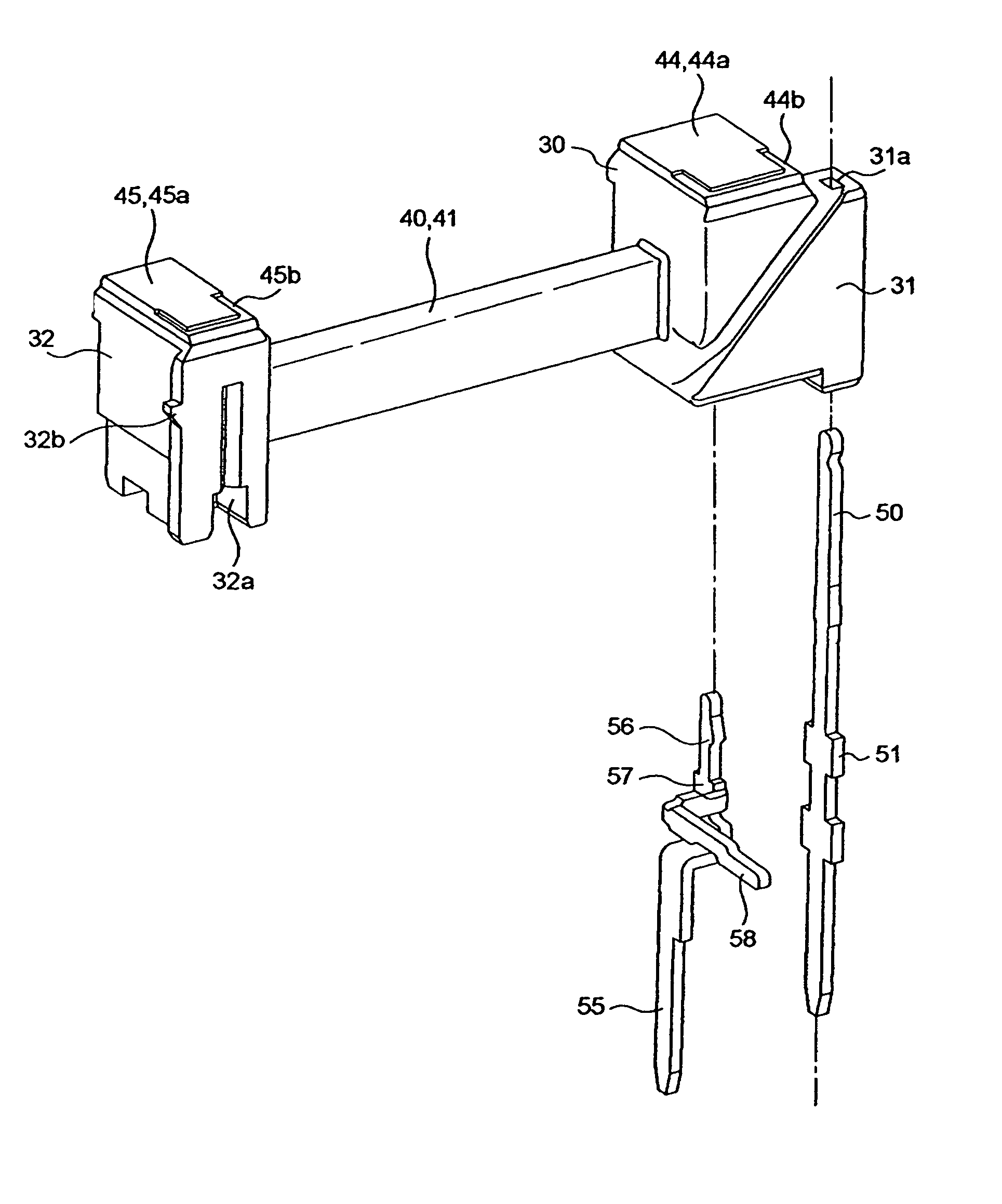
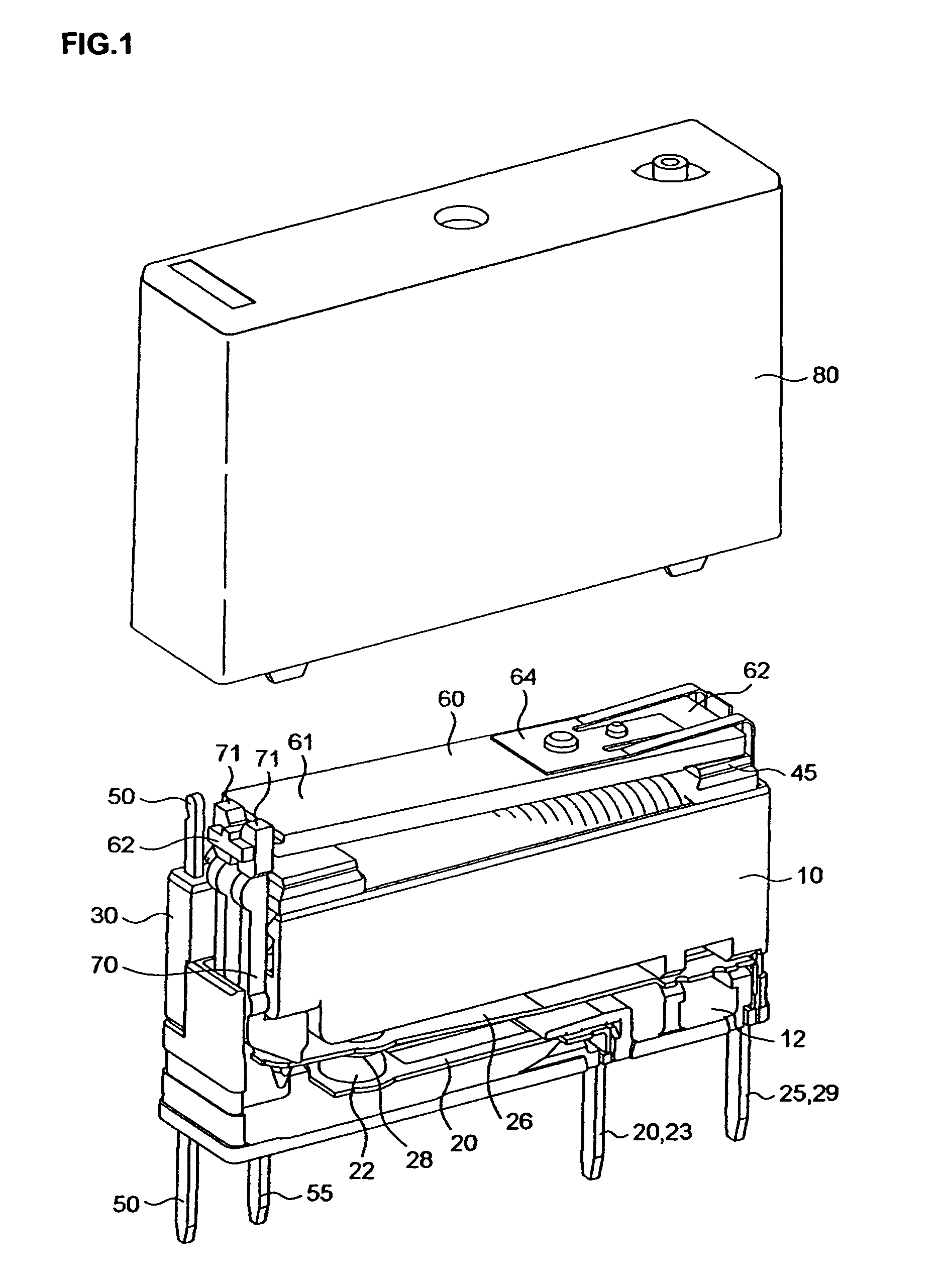
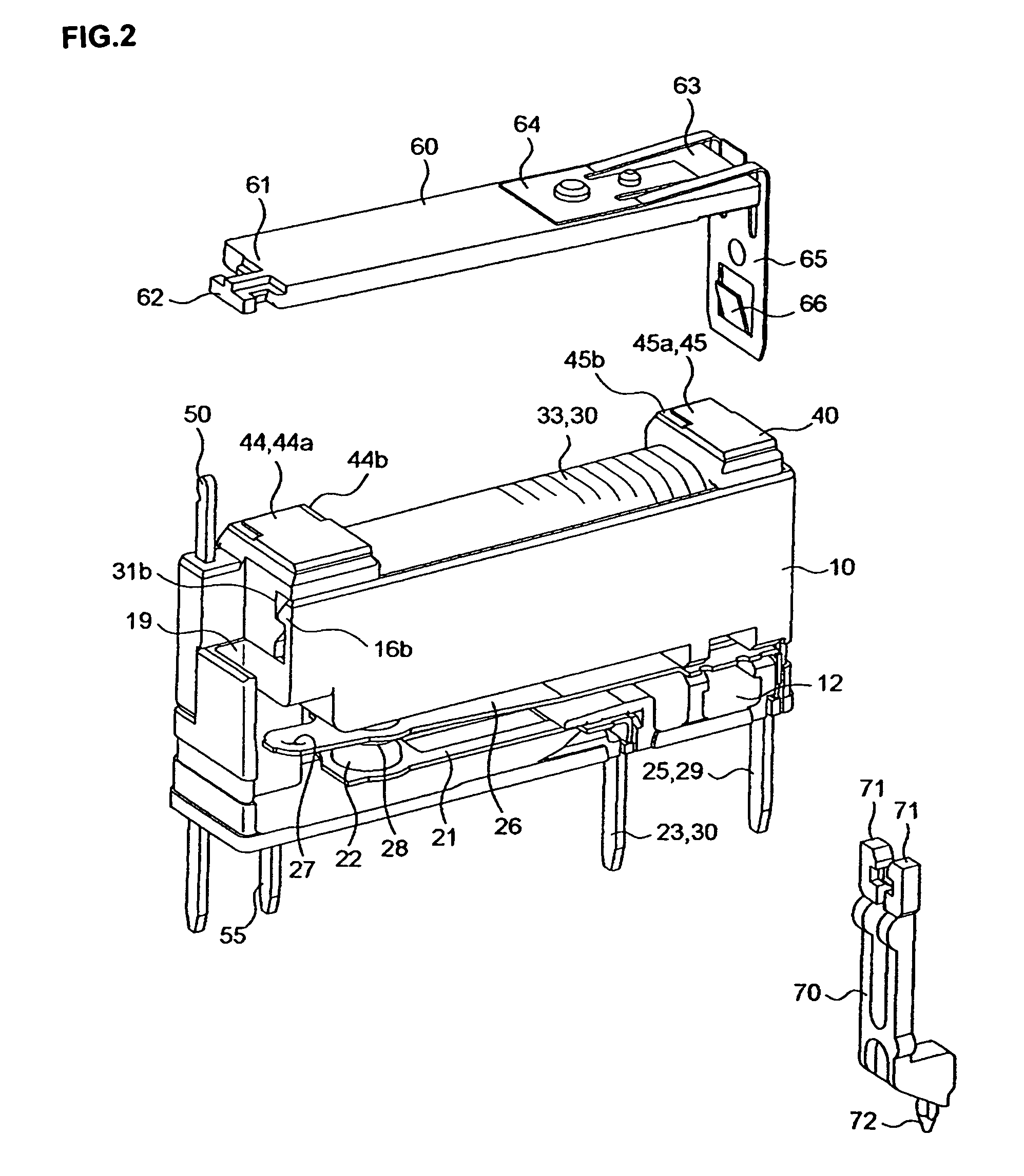
[0022]As illustrated in FIGS. 1 through 11, an electromagnetic relay in a first embodiment includes a base 10, a fixed contact terminal 20, a movable contact terminal 25, an electromagnet block 30, a movable iron fragment 60, a card 70, and a case 80. A housing of the electromagnetic relay in accordance with one embodiment of the invention is 5 mm in width, 12.5 mm in height and 20 mm in length.

[0023]The base 10 has an insulating partition wall 11 (FIG. 7) which is formed integrally with the base 10. The insulating partition wall 11 has a substantially U-shaped cross section which opens to the side of an intermediate portion of the base 10, and provides a lower space 12 and an upper space 13 both of which open to the opposite sides. As illustrated in FIG. 3, press-fit grooves 14 and 15 to which the fixed contact terminal 20 and the movable c...


PUM


Abstract

An electromagnetic relay which is short in length and capable of maintaining a required insulation distance is disclosed. A first coil terminal connecting with one of extension lines of a coil is disposed in the vicinity of one end of a movable iron fragment and a card. A second coil terminal having a binding member which extends from an intermediate portion of the second coil terminal in a horizontal direction and is allowed to be bended toward the electromagnet block with the other of the extension lines of the coil bound to the binding member is further disposed below the electromagnet block.

Description

FIELD OF THE INVENTION[0001]The present invention relates to an electromagnetic relay, and more particularly to disposition of coil terminals in an electromagnetic relay having a short length.BACKGROUND ART[0002]An example of a conventional electromagnetic relay is shown in FIGS. 14A and 14B. As illustrated in these figures, an electromagnet block 3 is formed by winding a coil 2 around a barrel of an iron core 1 which is substantially U-shaped as viewed from the front. One end 4a of a movable iron fragment 4 is rotatably supported by one magnetic pole 1a of the iron core 1, and the other end 4b of the movable iron fragment 4 is opposed to the other magnetic pole 1b of the iron core 1 such that the other end 4b can be attracted to the other magnetic pole 1b (see JP-A-2001-155610). A card 5 is vertically moved by an engaging claw 4c which extends from the other end 4b of the movable iron fragment 4 rotatable in accordance with energization and de-energization of the electromagnet bloc...

Claims


Application Information

Patent Timeline
Patent Type & Authority Patents(United States)
IPC IPC(8): H01H51/22H01H50/02H01H51/00H01H50/44H01H50/64
CPCH01H50/443H01H50/026
Inventor MINOWA, RYOTAYANO, KEISUKEHIROKI, KAZUCHIKAYOKOTE, YASUHIRO
Owner ORMON CORP
Why Eureka
Try Eureka