Electrochromic safety glazing
a technology of safety glazing and electrochromic devices, applied in the field of electrochromic glazing, can solve the problems of limiting the type of transparent conductors and other coatings that can be used with electrochromic devices, compromising their ability to impart safety attributes, and unsatisfactory mandated use of tempered glass
- Summary
- Abstract
- Description
- Claims
- Application Information
AI Technical Summary
Benefits of technology
Problems solved by technology
Method used
Image
Examples
example 1
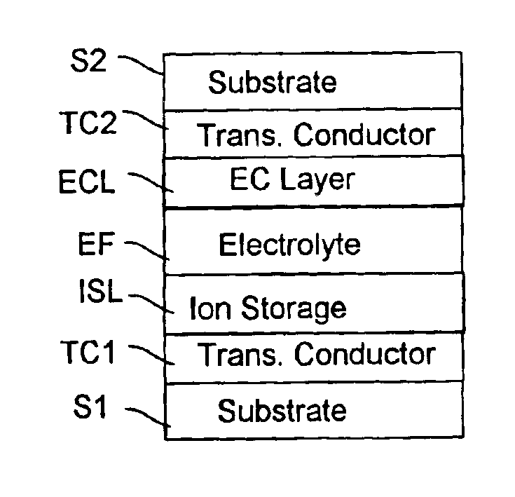
[0046]An electrolyte was made according to the teaching of this application with the following composition in which as EK 10 and EK 64 are exemplary experimental materials produced by BASF following the teaching of EP 1056097.
[0047]
EK1030% UV stabilized27.7% Tetraglyme5.3%37% fumedPMMALiClO4SiO2
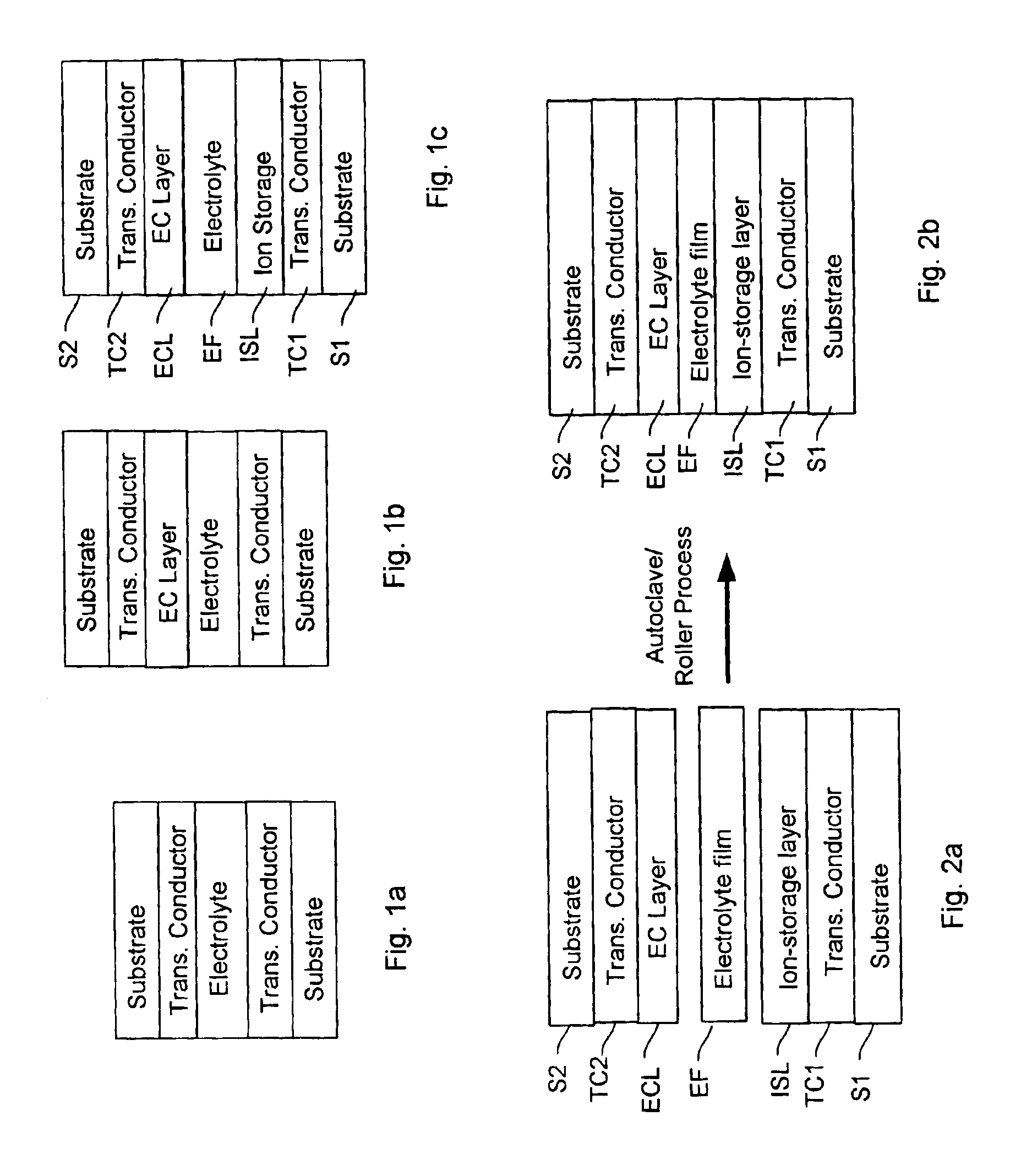
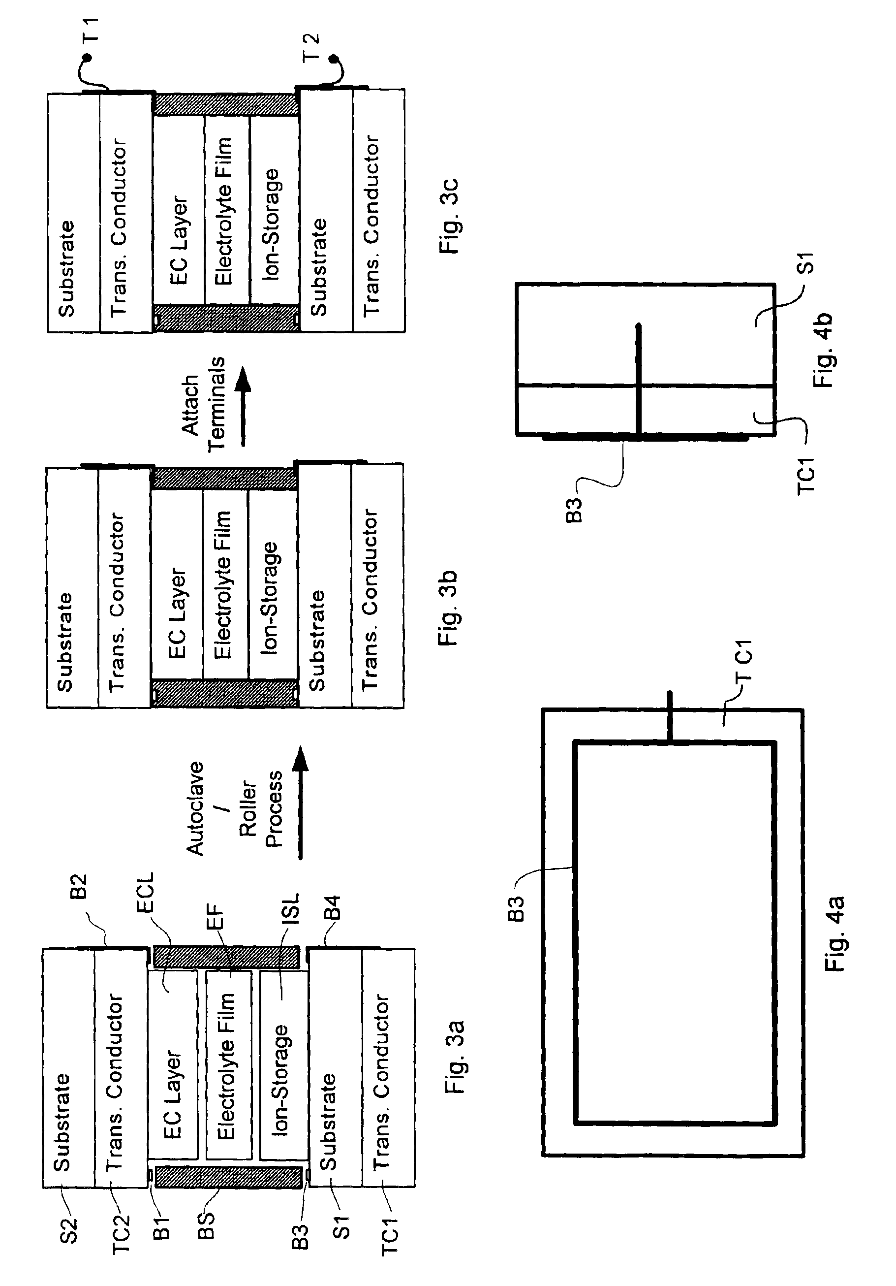
[0048]The above electrolyte was laminated between two 2″×2″ Tec 15 glass plate substrates (conductive side facing inwards) as described below:[0049]1. Out of substrate stock, two 2″×2″ squares of substrates are cut to size.[0050]2. Two ⅛″ wide bus bar strips are soldered to one end of each of the two substrates. Wire leads are soldered to bus bars.[0051]3. A 2″×1¾″ rectangular piece of solid polymer electrolyte EK10 is cut to size (electrolyte thickness=850 μm).[0052]4. The SPE (Solid Polymer Electrolyte) was laid on the first substrate.[0053]5. The substrates and the SPE are assembled with a ¼″ offset with the bus bars on opposite sides.[0054]6. The assembly is then vacuum sealed in a flexib...
example 2
[0060]Another clear electrolyte composition which was extruded is described below
[0061]
σ mS · cm−1σ mS · cm−1σ mS · cm−1Electrolyte(20° C.)(0° C.)(−20° C.)EK633.6 × 10−41. × 10−42 × 10−5
[0062]This consisted of 14% UV stabilized PVB, 14% UV stabilized PMMA, 33% tetraglyme, 4% LiClO4 and 35% SiO2 (all % by weight). The residual current for this film at 85 C at 1.5V was 1.3×10⁻⁶ A / sq. cm. The elongation to failure of this film was 670% and its strength to break was 10 kg / cm2. The film thickness was 600 micro-meters. This film when tested for adhesion on tungsten oxide according to ASTM D3167 yielded 30 pounds / linear inch width (5.4 kg / linear cm width). The film was supported by a backing film as the electrolyte film's adhesion exceeded the force that this film could bear before failure.
[0063]A laminate was produced with a 0.093 inch thick TEC15 glass coated with 350 nm thick tungsten oxide on the conductive side which was laminated to a 0.125 inch thick TEC8 piece of glass coated with ...
PUM
| Property | Measurement | Unit |
|---|---|---|
| pressure | aaaaa | aaaaa |
| elongation to failure | aaaaa | aaaaa |
| frequency | aaaaa | aaaaa |
Abstract
Description
Claims
Application Information
 - R&D
- Intellectual Property
- Life Sciences
- Materials
- Tech Scout
- Unparalleled Data Quality
- Higher Quality Content
- 60% Fewer Hallucinations
Browse by: Latest US Patents, China's latest patents, Technical Efficacy Thesaurus, Application Domain, Technology Topic, Popular Technical Reports.
© 2025 PatSnap. All rights reserved.Legal|Privacy policy|Modern Slavery Act Transparency Statement|Sitemap|About US| Contact US: help@patsnap.com


