Position measuring device and a method for operating a position measuring device

a position measuring and position technology, applied in the direction of speed measurement using gyroscopic effects, gyroscope/turn-sensitive devices, transmission systems, etc., can solve the problems of relatively difficult decoding of superimposed signals and inability to direct measurement with incremental position measuring devices, and achieve the effect of simple manner

Inactive Publication Date: 2006-02-07
DR JOHANNES HEIDENHAIN GMBH
View PDF27 Cites 11 Cited by
  • Summary
  • Abstract
  • Description
  • Claims
  • Application Information

AI Technical Summary

Benefits of technology

[0012]It is an object of the present invention to disclose a position measuring device wherein, on the one hand, position information is present at the output, and in add

Problems solved by technology

A direct measurement is not possible with incremental position measuring devices, which issue two rectangular scanning signals whic

Method used


Image

  • Position measuring device and a method for operating a position measuring device
  • Position measuring device and a method for operating a position measuring device
  • Position measuring device and a method for operating a position measuring device

Examples


Embodiment Construction

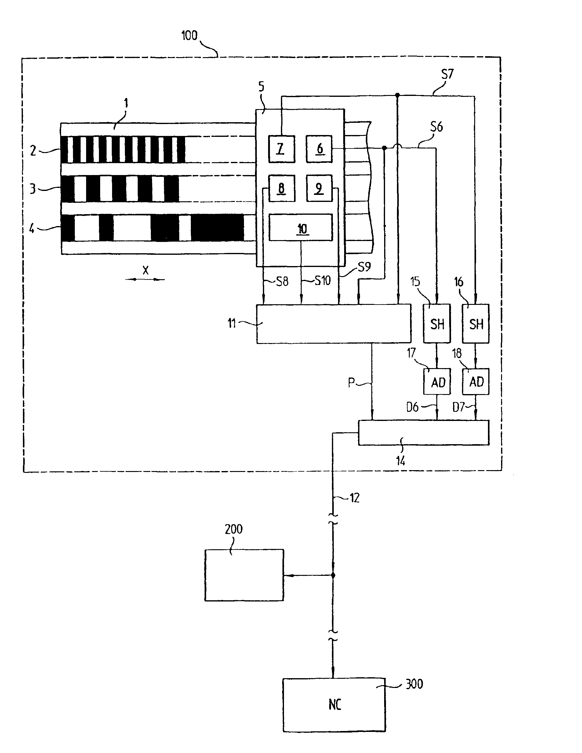
[0022]The absolute position measuring device 100 including a known manner for example of a scale 1 with several measuring graduations 2, 3, 4. The measuring graduations 2 and 3 are periodic graduations with different graduation periods, and the measuring graduation 4 is a non-periodic graduation, also called pseudo random code. Such a position measuring device is described in DE 41 23 722 A1.

[0023]The measuring graduations 2, 3, 4 are scanned by a common scanning head 5. The scanning head 5 contains scanning elements 6 to 10 for scanning the measuring graduations 2 to 4. The scanning elements 6 and 7 are assigned to the finest periodic measuring graduation 2 and each generates a sinusoidal analog scanning signal S6, S7 on its output, wherein the scanning signals S6 and S7 are phase-shifted by 90° in relation to each other. The periodic measuring graduation 3 is also scanned by scanning elements 8, 9 for the generation of two scanning signals S8 and S9, phase-shifted by 90° in relati...


PUM


Abstract

A position measuring device having a scanning element assigned to a periodic measuring graduation, the scanning element moves relative to the measuring graduation so as to scan the measuring graduation and generates a first analog signal and a second analog signal that is phase shifted relative to the first analog signal. A module that forms a measured position value, wherein the first and second analog signals are present at the module, and a code word defines a position that is present at an output of the module. An output module that digitally outputs the code word over a data channel and a conversion device that converts the first analog signal and the second analog signal into multi-digit amplitude-proportional code words, wherein the code words are also available at the output module for outputting on the data channel and is digitally transmitted by the output module over the data channel.

Description

[0001]Applicants claim, under 35 U.S.C. §§ 120 and 365, the benefit of priority of the filing date of Oct. 10, 2001 of a Patent Cooperation Treaty patent application, copy attached, Ser. No. PCT / EP01 / 11688, filed on the aforementioned date, the entire contents of which are incorporated herein by reference, wherein Patent Cooperation Treaty patent application Ser. No. PCT / EP01 / 11688 was not published under PCT Article 21(2) in English.[0002]Applicants claim, under 35 U.S.C. § 119, the benefit of priority of the filing date of Oct. 12, 2000 of a German patent application, copy attached, Ser. No. 100 50 392.6, filed on the aforementioned date, the entire contents of which are incorporated herein by reference.BACKGROUND OF THE INVENTION[0003]1. Field of the Invention[0004]The present invention relates to a position measuring device, and to a method for operating a position measuring device.[0005]2. Description of the Related Art[0006]A differentiation is made in connection with position...

Claims


Application Information

Patent Timeline
IPC IPC(8): G06F15/00G08C15/06G01D3/08G01D5/245G01D18/00G08C25/00
CPCG01D18/00G01D3/08
Inventor BRAASCH, JANHOFBAUER, HERMANNMITTMANN, RUDOLFSTRASSER, ERICHTONDORF, SEBASTIAN
Owner DR JOHANNES HEIDENHAIN GMBH
Why Eureka
Try Eureka