Automatic faucet control device and control method

a technology of automatic control device and control method, which is applied in water installations, urinals, constructions, etc., can solve the problems of high gloss of ceramics, inconvenient use, and water running, and achieve the effect of preventing erroneous sensing and reducing the siz

Inactive Publication Date: 2006-02-14
TOTO LTD
View PDF8 Cites 54 Cited by
  • Summary
  • Abstract
  • Description
  • Claims
  • Application Information

AI Technical Summary

Benefits of technology

[0017]In the automatic control device, the first and the second polarization means are polarizing plates provided so that their planes of polarization perpendicularly cross each other. Therefore, the automatic faucet control device does not have a larger size compared with a conventional infrared sensor, and it prevents erroneous sensing while maintaining the advantages of the infrared sensor.

Problems solved by technology

However, even if the washbasin is made of a ceramic, some kinds of ceramics are highly glossy.
As a result, the sensor erroneously senses the washbasin, the sink or the like as an object such as a hand, and thus the automatic faucet erroneously allows water to run.
Accordingly, it is extremely inconvenient to use.
However, they are effective only for small specular reflection.
Thus, in practice, only the limited types of washbasin or sink can be used in combination with the automatic faucet.
Moreover, the effects cannot be confirmed until the device is placed.
However, a sensor for the automatic faucet needs perfect waterproofing property, and the sensor is not allowed to have large size in view of design of the faucet.
Therefore, it has been an important issue to eliminate the effects of specular reflection.

Method used


Image

  • Automatic faucet control device and control method
  • Automatic faucet control device and control method
  • Automatic faucet control device and control method

Examples


Embodiment Construction

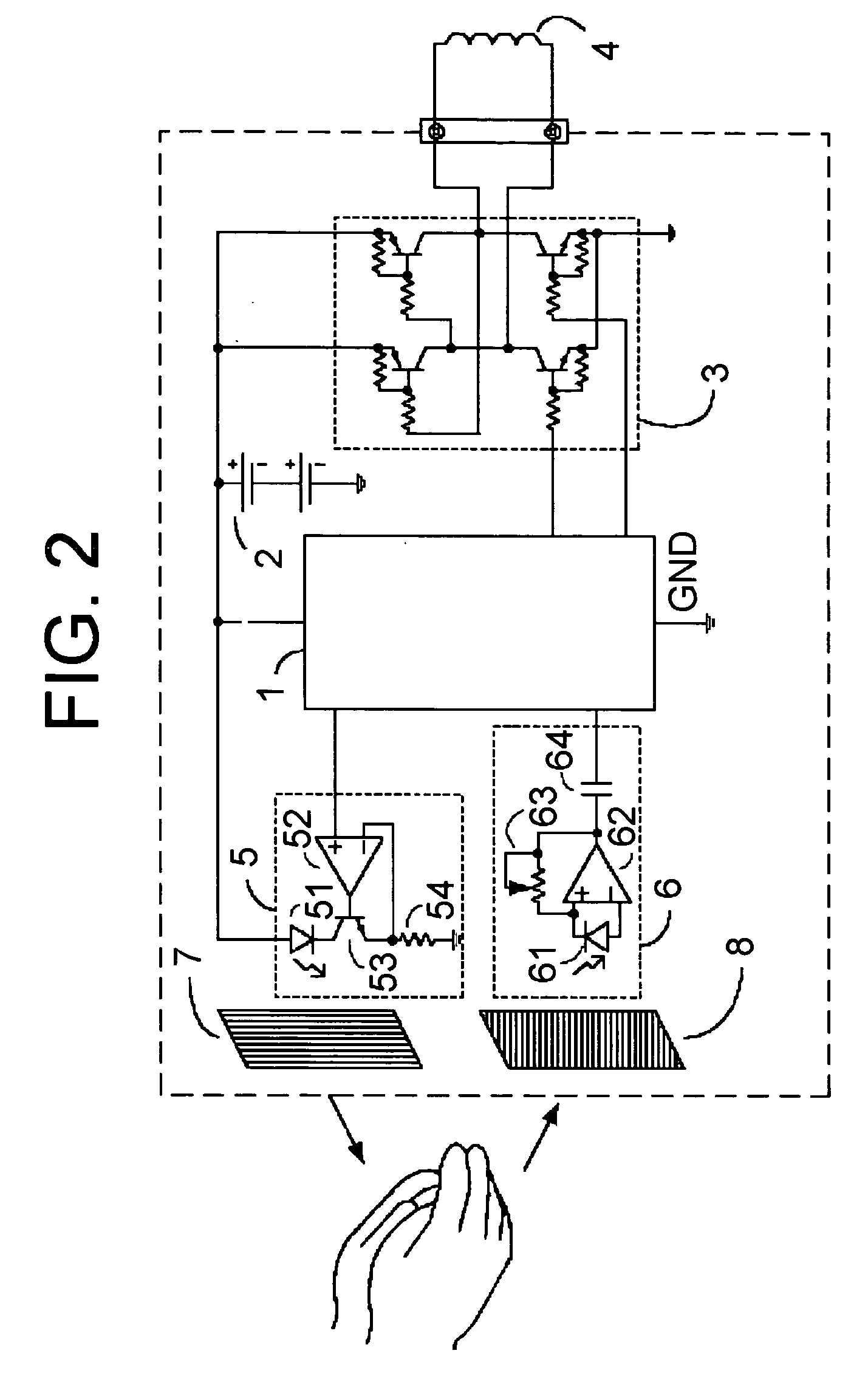
[0025]The present invention will be described in detail based on an embodiment shown in FIGS. 2 to 5. FIG. 2 is a view showing the configuration of an automatic faucet control device according to the present invention. In FIG. 2, the reference numeral 1 denotes a microcomputer which controls all operations of an automatic faucet, such as driving of an infrared sensor, sensing decision processing of the sensor, and driving of an electromagnetic valve based on the result of sensing. The reference numeral 2 denotes a battery serving as a power source; the reference numeral 4 denotes a solenoid corresponding to the electromagnetic valve for opening and closing a water channel of the automatic faucet; and the reference numeral 3 denotes a solenoid energizing circuit for energizing the solenoid 4.

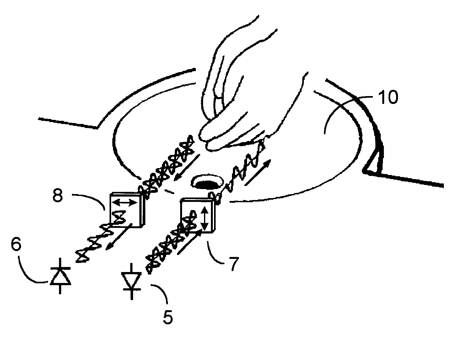
[0026]The reference numerals 5 and 6 constitute ray emitting and receiving sections of the infrared sensor. The reference numeral 5 denotes a ray emitting section (ray emitting means) of the sens...


PUM


Abstract

An automatic faucet control device including an electromagnetic valve for opening and closing a flow channel of a faucet, a ray emitting device (5) for emitting infrared rays to a target to be detected, a ray receiving device (6) for receiving the infrared rays reflected by the target, a sensing decision device for the deciding presence or absence of the target by an output from the ray receiving device (6), and an electromagnetic valve controller for controlling the electromagnetic valve based on a signal from the sensing decision device. The ray emitting device (5) has a first polarizing plate (7) allowing a polarized light component to be transmitted, and the ray receiving device (6) has a second polarizing plate (8) for allowing a polarized light component different from the rays transmitted through the first polarizing plate (7) to be transmitted therethrough.

Description

TECHNICAL FIELD[0001]The present invention relates to an automatic faucet control device used for hand-washing or the like, which detects an object to allow water to automatically run, and to a control method.BACKGROUND ART[0002]An automatic faucet detects user's hands in a toilet or lavatory and a dish or a pan in a kitchen or the like to allow water to automatically run. Such an automatic faucet is widely used because of its convenience, cleanness, water-saving performance, and the like. As a sensor mounted to the automatic faucet to detect an object for which the water is allowed to run, an infrared sensor is used in almost all the cases.[0003]Not only the automatic faucets but any faucet device is attached to a device for receiving running water and draining it, for example, to a washbowl or a washbasin in a toilet and to a sink in a kitchen.[0004]FIG. 1 is a cross-sectional view showing a state where an automatic faucet according to a conventional example is attached to a washb...

Claims


Application Information

Patent Timeline
Patent Type & Authority Patents(United States)
IPC IPC(8): E03C1/05
CPCE03C1/057
Inventor KANEKO, YOSHIYUKI
Owner TOTO LTD
Why Eureka
Try Eureka