Secondary containment leak prevention and detection system and method

a detection system and leak prevention technology, applied in the direction of instruments, fluid-tightness measurement, liquid transferring devices, etc., can solve the problems of detection alarm generated, fuel piping outer wall leakage, and shutting down of stp

Inactive Publication Date: 2006-02-14
VEEDER ROOT
View PDF63 Cites 12 Cited by
  • Summary
  • Abstract
  • Description
  • Claims
  • Application Information

AI Technical Summary

Benefits of technology

[0012]If the vacuum level in the outer annular space is restored to the defined initial threshold vacuum level within a defined period of time, a precision leak detection test is performed. The sensing unit monitors the vacuum level in the outer annular space to determine if the vacuum level decays to a precision threshold vacuum level within a defined period of time, in which case a precis

Problems solved by technology

If the outer annular space cannot maintain a pressure or vacuum level over a given amount of time after being pressurized, this is indicative that the outer wall of the fuel piping contains a breach

Method used


Image

  • Secondary containment leak prevention and detection system and method
  • Secondary containment leak prevention and detection system and method
  • Secondary containment leak prevention and detection system and method

Examples


Embodiment Construction

[0036]The embodiments set forth below represent the necessary information to enable those skilled in the art to practice the invention and illustrate the best mode of practicing the invention. Upon reading the following description in light of the accompanying drawing figures, those skilled in the art will understand the concepts of the invention and will recognize applications of these concepts not particularly addressed herein. It should be understood that these concepts and applications fall within the scope of the disclosure and the accompanying claims.

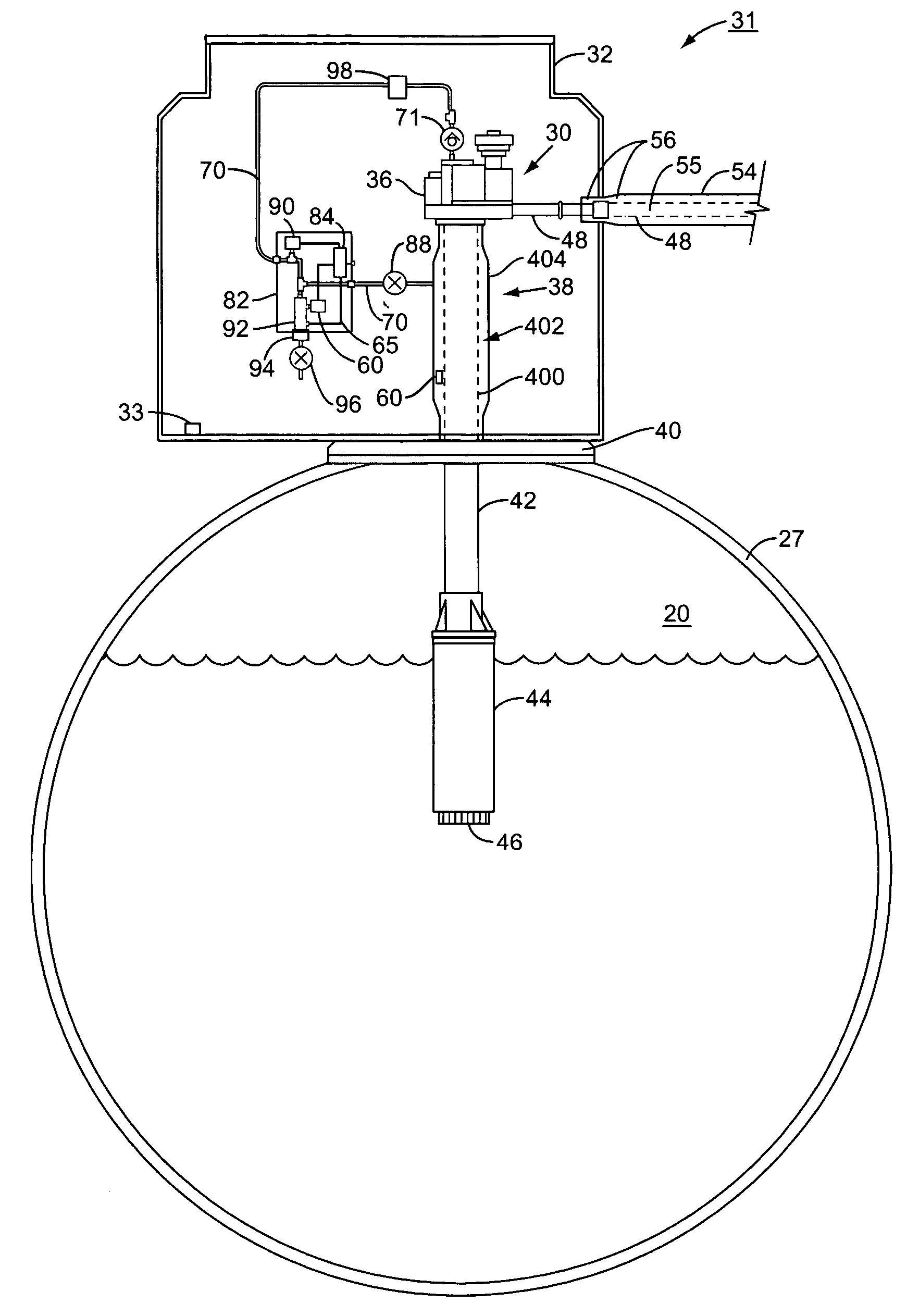
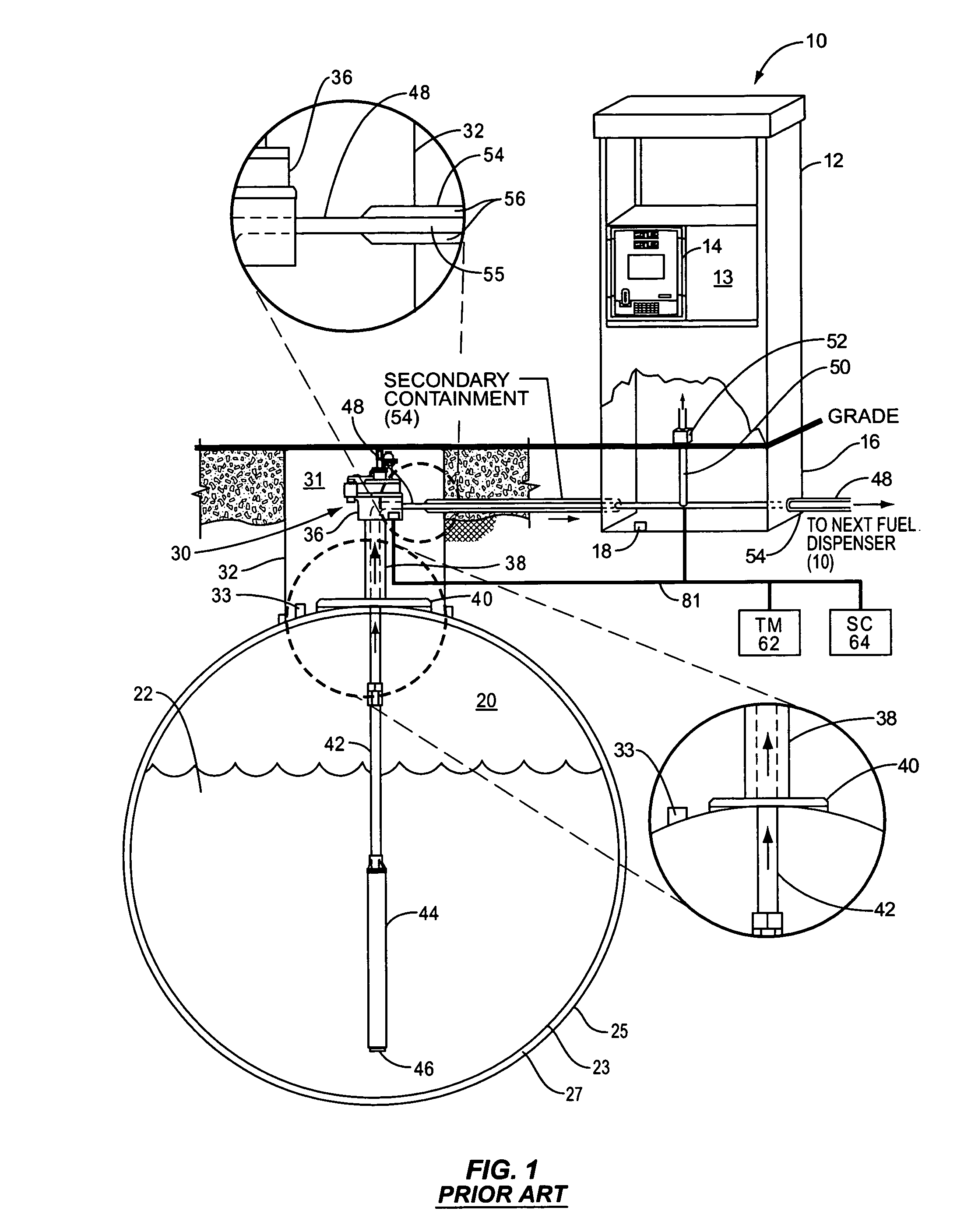
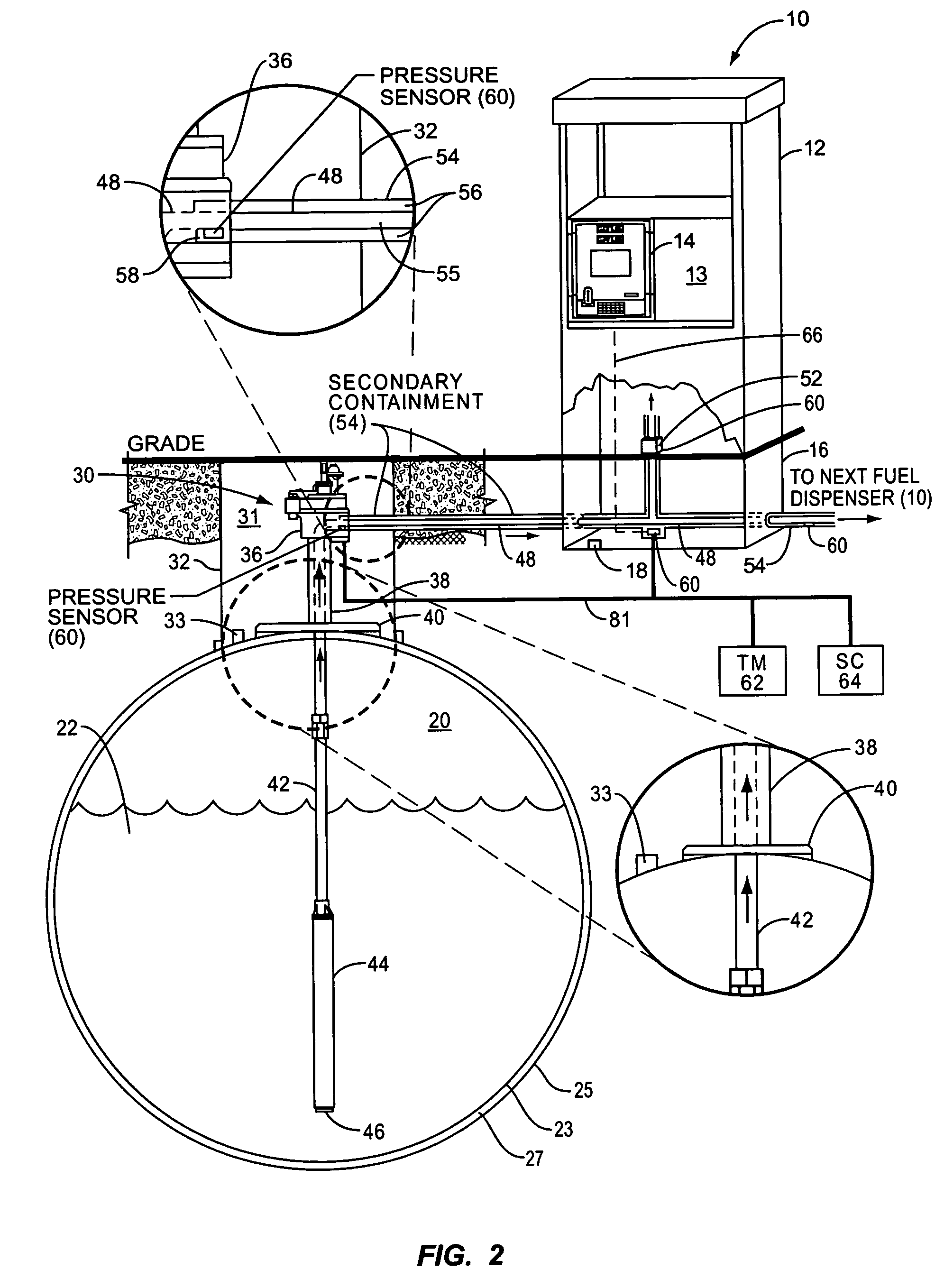
[0037]FIGS. 1–8 represent the disclosures made in the parent applications. This background material may be helpful to understand some of the details of the creation of a vacuum in an interstitial space and the sensing that accompanies this vacuum that is used to determine if there is a leak. The discussion of the present invention begins with the discussion of FIG. 9; however, it should be appreciated that the teachings of the sen...


PUM


Abstract

A pump housing contains a pump that draws fuel from an underground storage tank to deliver fuel to fuel dispensers in a service station environment. The pump is coupled to a double-walled riser pipe that carries the fuel from the underground storage tank to the pump. The double-walled fuel piping contains an inner space that carries the fuel and an outer annular space that captures any leaked fuel from the inner space. The outer annular space is coupled to a vacuum created by the pump to determine if a leak exists in the outer annular space. An alternate submersible turbine pump has a double-walled housing with a pressure sensor disposed in the interstitial space of the double-walled housing. A vacuum may be created therein to determine if leaks are present in the housing of the submersible turbine pump.

Description

RELATED APPLICATIONS[0001]This patent application is a continuation-in-part application of patent application Ser. No. 10 / 430,890, filed on May 6, 2003, which is a continuation-in-part of patent application Ser. No. 10 / 238,822, filed on Sep. 10, 2002, both of which are hereby incorporated by reference in their entireties.[0002]Patent application Ser. No. 10 / 390,346 entitled “Fuel Storage Tank Leak Prevention and Detection System and Method,” filed on Mar. 17, 2003, now U.S. Pat. No. 6,834,534, and including the same inventors as included in the present application is related to the present application and is also incorporated herein by reference in its entirety.FIELD OF THE INVENTION[0003]The present invention relates to detection of a leak or breach in the secondary containment of a riser pipe associated with a submersible turbine pump and / or the submersible turbine pump housing in a retail service station environment.BACKGROUND OF THE INVENTION[0004]In service station environments...

Claims


Application Information

Patent Timeline
IPC IPC(8): G01M3/28G01M3/26B65D88/76B65D90/501B65D90/503B67D7/32B67D7/66B67D7/68B67D7/78
CPCB65D88/76B65D90/501B65D90/503G01M3/2892B67D7/66B67D7/68B67D7/78B67D7/3209Y10T137/0402
Inventor HUTCHINSON, RAY J.HALLA, DONALD D.DOLSON, RICHARD G.HART, ROBERT P.LUCAS, RICHARD K.REID, KENT D.
Owner VEEDER ROOT
Why Eureka
Try Eureka