Electronic voting system and method of preventing unauthorized use of ballot cards therein

Inactive Publication Date: 2006-02-14
NEC CORP
View PDF7 Cites 4 Cited by
  • Summary
  • Abstract
  • Description
  • Claims
  • Application Information

AI Technical Summary

Benefits of technology

[0008]It is an object of the present invention to provide an electronic voting system which can prevent the unauthorized use of a ballot card, e.g., taking the ballot card out of a polling place and transferring it to the third person, a method of preventing the unauthorized use of a ballot card in the system, and a storage medium recording a program for preventing the unauthorized use of a ballot card.
[0009]It is another object of the present invention to provide an electronic voting system which can discriminate a case wherein voting could not be performed because of a faulty ballot card from a case wherein a voter intentionally broke or lost a ballot card and claims that he / she could not cast a vote, and prevent double voting by unauthorized reissuance of a ballot card, a method of preventing the unauthorized use of a ballot card in the system, and a storage medium recording a program for preventing the unauthorized use of a ballot card.

Problems solved by technology

The following problems, however, arise in such a conventional electronic voting system.
This leads to the purchase of votes.
In spite of fact that voting has been completed by inserting a ballot card into the voting apparatus, some person may intentionally break the ballot card and claim that he / she could not cast a vote.
However, it is impossible to discriminate them.

Method used


Image

  • Electronic voting system and method of preventing unauthorized use of ballot cards therein
  • Electronic voting system and method of preventing unauthorized use of ballot cards therein
  • Electronic voting system and method of preventing unauthorized use of ballot cards therein

Examples


first embodiment

[0024]the present invention will be described in detail next with reference to the accompanying drawings.

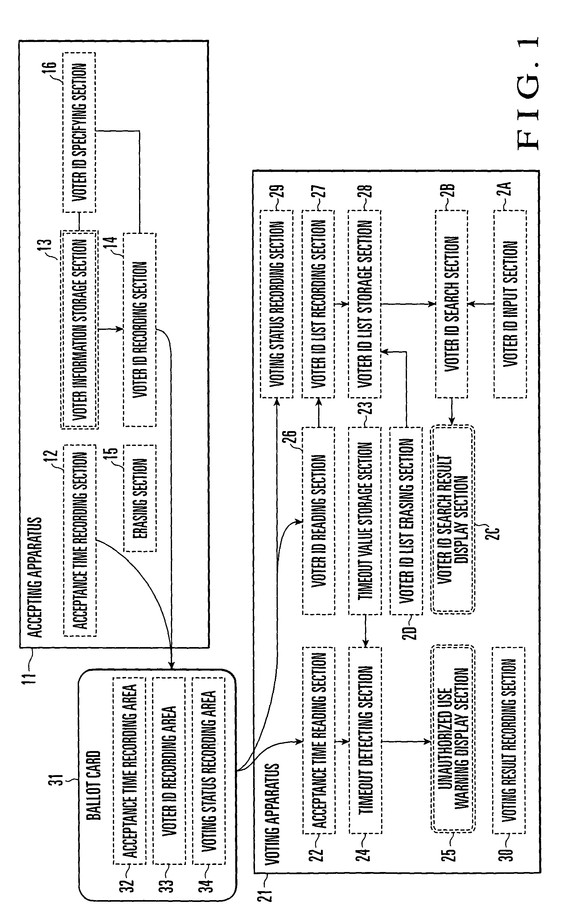
[0025]As shown in FIG. 1, an electronic voting system according to this embodiment is comprised of an accepting apparatus 11, voting apparatus 21, and ballot card 31.

[0026]The accepting apparatus 11 includes an acceptance time recording section 12, a voter information storage section 13, a voter ID recording section 14 connected to the voter information storage section 13, and an erasing section 15. The acceptance time recording section 12 writes the current time in an acceptance time recording area 32 of the ballot card 31 (to be described later).

[0027]On the voter information storage section 13, voter information, e.g., information (voter ID) for uniquely identifying a voter is recoded. When a ballot card (to be described later) is inserted, the voter ID recording section 14 retrieves information (voter ID) for uniquely identifying the voter who has completed an acceptance proc...

second embodiment

[0095]the present invention will be described next in detail with reference to FIG. 10.

[0096]An electronic voting system of this embodiment provides another method of inputting a voter ID in checking whether or not a voter ID as a search target is stored in a voter ID list storage section 28 of a voting apparatus 21. The remaining arrangements are the same as in the first embodiment.

[0097]In the first embodiment, a voter ID is manually input from the touch panel. In the second embodiment, an accepting apparatus 11 issues a voter ID checking card 41 for checking a voter ID, and the card is inserted into the voting apparatus 21 to allow the voting apparatus 21 to recognize the voter ID as a search target.

[0098]A checking identifier 41a and checking voter ID 41b are recoded on the voter ID checking card 41. The checking identifier 41a indicates information for identifying the checking card. The checking voter ID 41b indicates a voter ID as a search target.

[0099]The accepting apparatus ...

third embodiment

[0102]the present invention will be described in detail next with reference to the accompanying drawings.

[0103]As shown in FIG. 12, an electronic voting system according to this embodiment has an arrangement in which voting apparatuses 211 to 21n are connected through a network 80. Each of the voting apparatuses 211 to 21n has the same arrangement as that of the voting apparatus 21 described above.

[0104]In this electronic voting system, a voter ID search section 2B of each voting apparatus is designed to return a result with respect to a search request through the network 80. This makes it possible for one voting apparatus to search the voter IDs recorded on all the voting apparatuses.

[0105]The operation of the electronic voting system according to this embodiment will be described next with reference to FIG. 13.

[0106]The voting apparatus 211 reads the application specific identifier of a card therefrom (step G1). If this card is not a voter ID checking card (step G2: NO), normal vo...


PUM


Abstract

An electronic voting system includes a ballot card, accepting apparatus, and at least one voting apparatus. The accepting apparatus issues a ballot card in accordance with a vote acceptance request. The voting apparatus performs voting processing in accordance with a vote request using the ballot card. The accepting apparatus includes an acceptance time recording section which records the acceptance time on the ballot card when issuing the ballot card. The voting apparatus includes a timeout detecting section and unauthorized use warning display section. Before performing voting processing upon reception of a vote request, the timeout detecting section determines whether or not a preset timeout time has elapsed from the acceptance time recorded on the ballot card to the time of voting. The unauthorized use warning display section outputs a warning message when the timeout detecting section determines that the timeout time has elapsed.

Description

BACKGROUND OF THE INVENTION[0001]The present invention relates to an electronic voting system in which voting is electronically performed by a voting apparatus using a ballot card issued by an accepting apparatus and, more particularly, to an electronic voting system having a function of preventing unauthorized use of the ballot card, a method of preventing such unauthorized use, and a recording medium storing a program.[0002]Currently, voting in an election or the like is generally performed in the following manner. A front desk and ballot box are prepared in a polling place. In the polling place, a ballot sheet is handed to a person who has properly completed an acceptance procedure. The person then writes, on the ballot sheet, the name of a candidate for whom the person wants to vote, and casts the ballot sheet into the ballot box.[0003]Likewise, in a polling place where acceptance and voting procedures are separately performed, a ballot card is issued, instead of a ballot sheet,...

Claims


Application Information

Patent Timeline
IPC IPC(8): G07C13/00G06Q50/00G06Q50/10G06Q50/34
CPCG07F17/3288G06Q50/34
Inventor KONDOU, MAKOTO
Owner NEC CORP
Why Eureka
Try Eureka