Lifting apparatus

a technology of lifting apparatus and lifting rod, which is applied in the direction of lifting equipment, furniture parts, machine supports, etc., can solve the problems of difficult cleaning or reaching under the article, large and cumbersome, and difficult for a single person to lift or move the article, and achieves the effect of convenient use and inexpensive manufacturing

a technology of lifting apparatus and lifting rod, which is applied in the direction of lifting equipment, furniture parts, machine supports, etc., can solve the problems of difficult cleaning or reaching under the article, large and cumbersome, and difficult for a single person to lift or move the article, and achieves the effect of convenient use and inexpensive manufacturing

US6997424B2Inactive Publication Date: 2006-02-14TITAN PROD LLC

Image

  • Lifting apparatus
  • Lifting apparatus
  • Lifting apparatus

Examples


Embodiment Construction

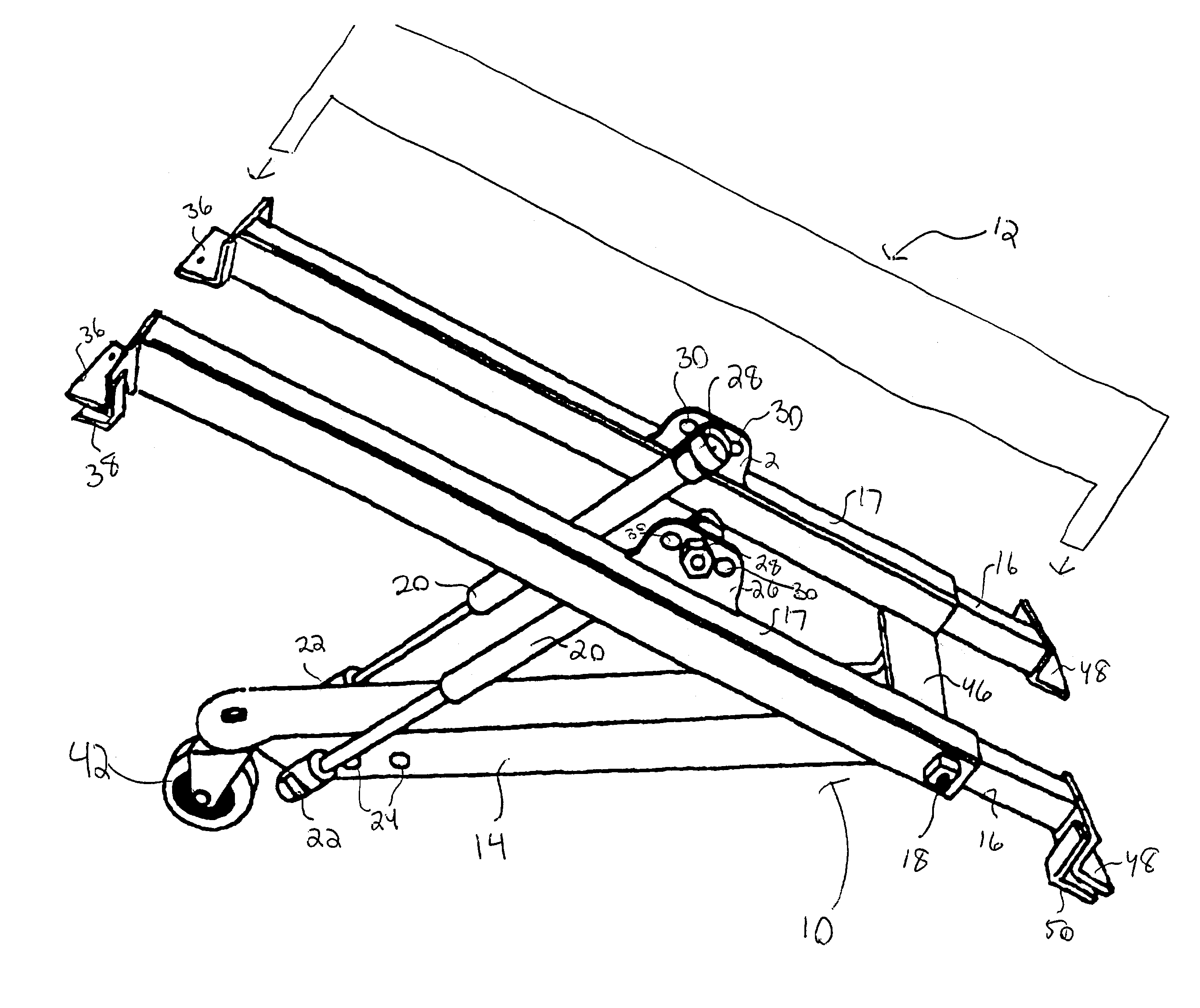
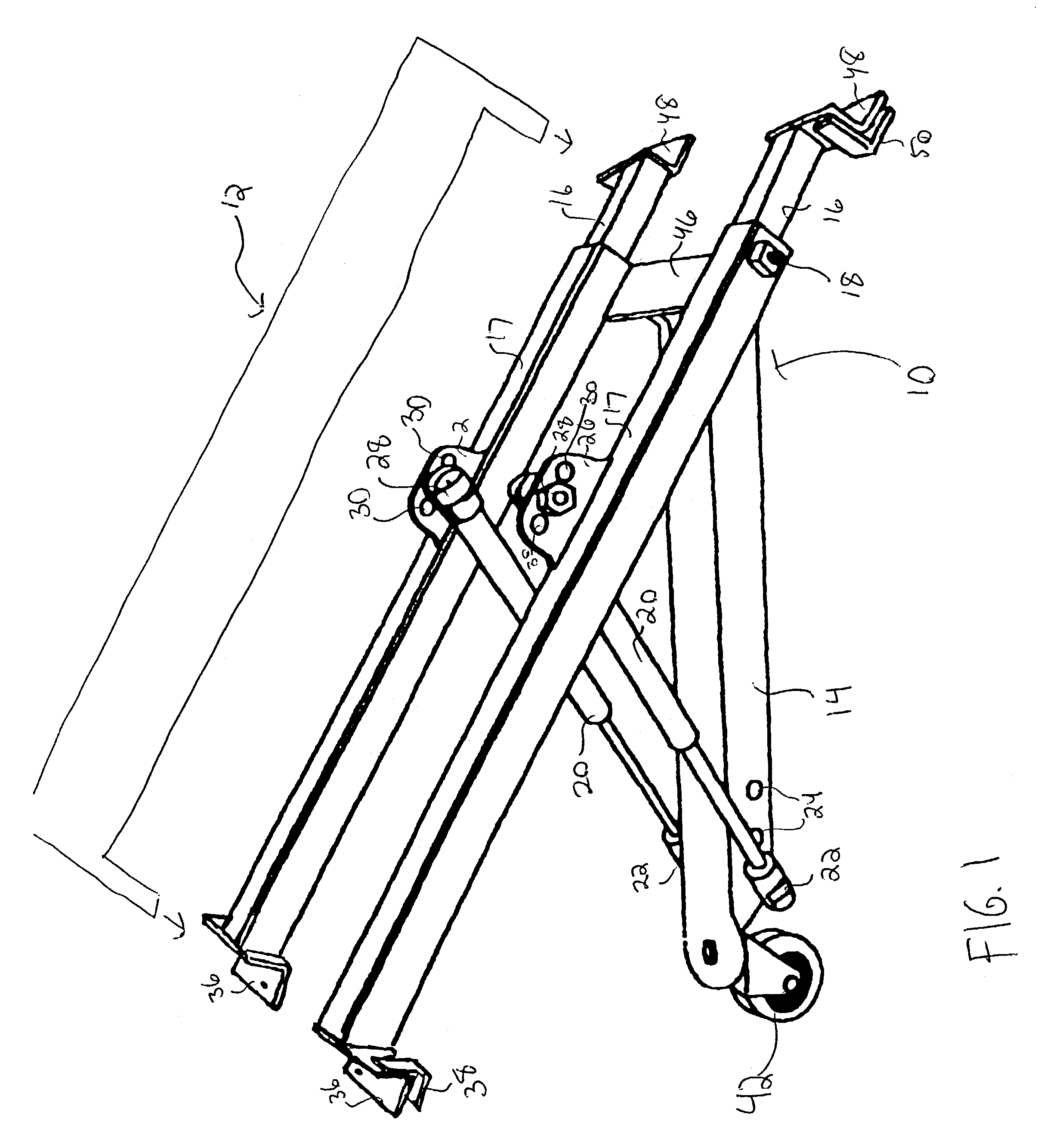
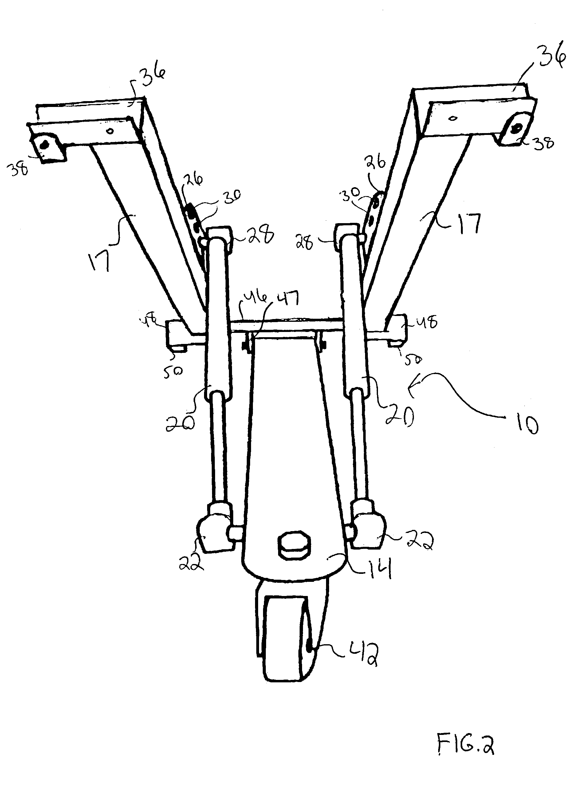
[0011]A device constructed according to the present invention is shown generally at 10 in FIGS. 1–4, according to a preferred embodiment of the invention, for lifting a heavy article, shown at 12 in FIG. 1, such as a piece of furniture. The device 10 comprises a primary member 14 operatively connected to one or more outer telescoping members 17, which are connected to one or more inner telescoping members 16. Each inner telescoping member 16 is coupled to a corresponding outer telescoping member 17 by a set screw 18 or similar fastener. The use of the set screw 18 permits the effective length of the inner telescoping member 16 and the outer telescoping member 17 to be adjusted in order for the device 10 to attach to articles 12 of different shapes and sizes.

[0012]In one embodiment of the invention, the primary member 14 is operatively connected to each outer telescoping member 17 by one or more biasing members 20. In a preferred embodiment of the invention, each biasing member 20 co...


PUM


Abstract

A device for lifting an item such as an article of furniture to gain access underneath for performing a variety of tasks. The device comprises a horizontal actuating beam attached via a hinge member to one or more horizontal support beams that are affixed to the object frame. The horizontal actuating beam is also connected to the one or more horizontal support beams by one or more biasing members. The horizontal actuating beam includes a pivoting axle at one end that is attached to the one or more horizontal support beams and a wheel at the other end that presses downward on a surface and acts as a support point when the front of the object is raised up off of the surface.

Description

CROSS-REFERENCE TO RELATED PATENT APPLICATIONS[0001]This application is a Non-Provisional of U.S. Application 60 / 455,639, filed Mar. 18, 2003, incorporated herein by reference in its entirety.FIELD OF THE INVENTION[0002]The present invention relates generally to a lifting apparatus. More particularly, the present invention relates to an apparatus for assisting a user in lifting heavy articles such as furniture.BACKGROUND OF THE INVENTION[0003]There are a number of situations, both in the home and at work, where a person must gain access to the underside of a heavy article. In the home, for example, a person must often lift a couch, sofa, or other piece of large and / or heavy furniture in order to retrieve items that have fallen beneath the article or to vacuum or clean the region underneath the article. In the case of a large couch or sofa, this can pose a number of safety and health issues. Some articles may weigh well over 100 pounds and may be so large and cumbersome that they are...

Claims


Application Information

Patent Timeline
14 Feb 2006
Publication
US6997424B2
IPC
A47B91/00; B66F7/22; B66F19/00
CPC
B66F19/00
Inventors
ATKINSON, JR., RONALD NEIL