Fail safe valve

a safe valve and valve element technology, applied in the direction of valve details, valve arrangement, pressure relieving devices on sealing faces, etc., can solve the problems of limited power transfer capacity, magnetic coupling, etc., and achieve the effect of accurate movement control of the valve element and small movemen

Active Publication Date: 2006-02-14
DANFOSS AS
View PDF10 Cites 16 Cited by
  • Summary
  • Abstract
  • Description
  • Claims
  • Application Information

AI Technical Summary

Benefits of technology

[0009]Through a combination of these three measures, the tightness of the valve can be ensured. The valve can be hermetically tight or sealed. The valve element is separated from the environment by the closed valve housing. The transfer of driving power takes place via the magnetic coupling. However, the amount of power, which can be transferred by means of a magnetic coupling, is limited. Accordingly, since a magnetic coupling is being employed the valve element must be movable using only a small amount of power. For this purpose, the valve element is pressure released, that is, measures are taken to ensure that substantially the same pressure is present on both sides of the valve element. These measures can, for example, be that a pressure-balancing channel is provided inside the housing or even inside the valve element, said channel acting upon both sides of the valve element with the same pressure. In this case, the valve element only has to overcome frictional forces. However, these frictional forces are small, as practically no external forces act upon the valve element. An advantage of the present invention is that due to the fact that the magnetic coupling does not need to transfer large forces, a relatively small and inexpensive control motor can be used.
[0010]Preferably, the control motor is a stepping motor. A stepping motor has the advantage that the position of the valve element can be determined by counting impulses supplied to the stepping motor. Additional sensors can also be used with the stepping motor.
[0011]Preferably, the magnetic coupling acts upon the valve element via a threaded connection. Thus, relatively accurate movement control of the valve element is achieved. At the same time, the movements of the valve element can be effected with extremely small forces. In operation, a first part of the threaded connection is turned that displaces another part of the threaded connection in an axial direction (in relation to the rotation of the first part of the threaded connection). Depending on the pitch of the thread defined by the threaded connection, very small movements are achieved per angular increment of the control motor. These movements can, for example, be about 5 / 100 mm per 2° of rotation.
[0012]Preferably, the valve element is non-rotatably retained, and the threaded connection includes a spindle screwed into the valve element or into a part connected with the valve element. This embodiment has the advantage that the valve element is only moved axially, that is, in the direction of the valve seat or away from the valve seat. These closing or opening movements, respectively, will not turn the valve element in relation to the valve seat.
[0013]Preferably, an adapter piece surrounds an outlet-side part of the magnetic coupling. This adapter piece can then be sized with a view to the fact that a transfer of magnetic forces through the adapter piece is possible. The adapter piece must also be able to withstand the pressures occurring in the refrigeration system or in the area of the valve. For example, the adapter piece can be made of a different material than the rest of the valve housing.
[0014]It is also preferable that the adapter piece is made of a magnetically non-conducting material. The adapter piece, which can, for example, be made of austenitic steel, then does not interfere with the power transfer between the two parts of the magnetic coupling.

Problems solved by technology

However, the amount of power, which can be transferred by means of a magnetic coupling, is limited.

Method used


Image

  • Fail safe valve
  • Fail safe valve
  • Fail safe valve

Examples


Embodiment Construction

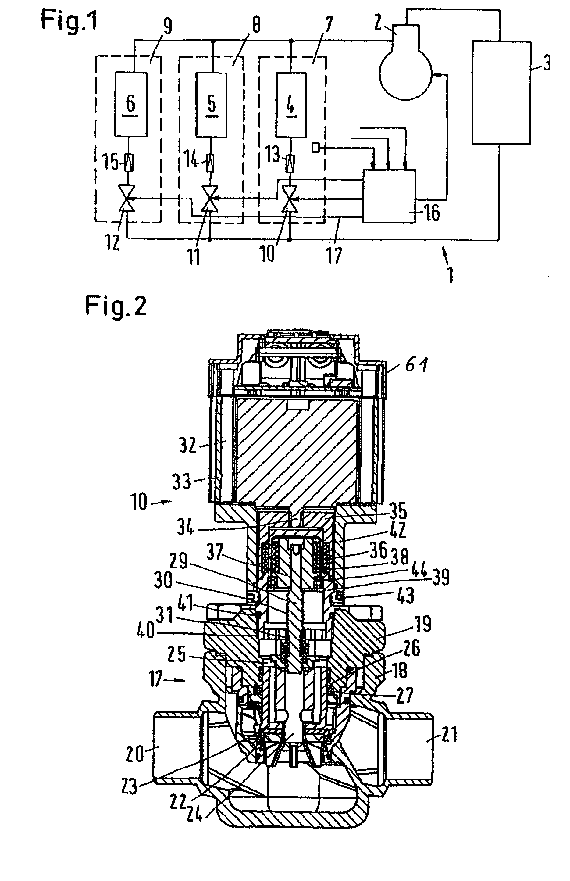
[0028]FIG. 1 schematically shows a refrigeration system 1 with a compressor 2, which supplies a refrigerant under high pressure and at a high temperature to a condenser 3. In the condenser 3 the refrigerant is cooled. Due to this cooling, the refrigerant converts to a fluid. The condenser 3 supplies three connected evaporators 4, 5 and 6, connected in parallel, each located in a cold room 7, 8 or 9, respectively. The connection between the condenser 3 and each evaporator 4, 5 and 6 takes place via a valve 10, 11 and 12 and a throttling member 13, 14 and 15. The throttling member can, for example, be a capillary tube or an expansion valve. For reasons of clarity, the valves 10, 11, and 12 are shown separately from the throttling members 13, 14 and 15. Usually, each valve 10, 11, and 12 is combined with the related throttling member 13, 14, and 15.

[0029]A control device 16 controls the valves 10, 11, and 12 and the compressor 2.

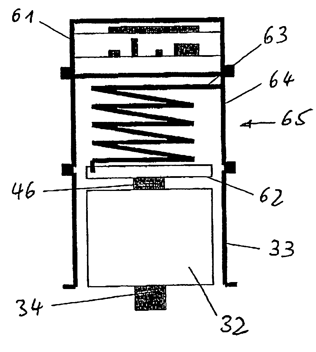
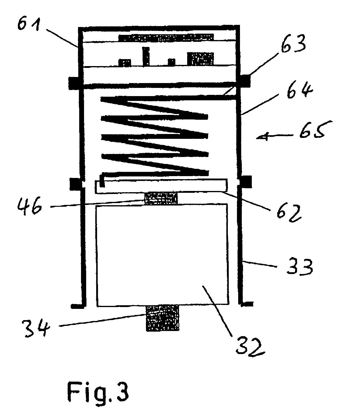
[0030]An example of a valve 10 is shown in FIG. 2. Such a...


PUM


Abstract

The invention concerns a fail-safe valve having a valve element, and a control motor being connected with the valve element via a driveline. It is endeavored to ensure the tightness of the refrigeration system in a simple manner. For this purpose, it is ensured that the valve element is located inside and the control motor outside a closed valve housing, that the drive line has a magnetic coupling, which acts through the housing, and that the valve element is pressure-released. In addition, a resetting device is provided that causes the valve element to be returned to a predetermined position upon the undesired cessation of control motor operation.

Description

CROSS-REFERENCE TO RELATED APPLICATIONS[0001]This application is entitled to the benefit of and incorporates by reference essential subject matter disclosed in German Patent Application No. 103 28 111.8 filed on Jun. 20, 2003 and German Patent Application No. 10 2004 028 865.8 filed Jun. 15, 2004.FIELD OF THE INVENTION[0002]The invention generally concerns a fail-safe valve having a valve element, and a control motor connected with the valve element, and is more particularly directed to a mechanism by which the valve element is returned to a predetermined position upon drive failure.BACKGROUND OF THE INVENTION[0003]In large refrigeration systems, for example those used in the industrial field, correspondingly large valves are required; each of whose valve elements is activated from the outside by a control motor. When displacing the valve element, a passage through the valve is further released or further throttled. Such a valve can also be closed. In this case, the valve element be...

Claims


Application Information

Patent Timeline
Patent Type & Authority Patents(United States)
IPC IPC(8): F16K31/04F16K31/56F16K39/02
CPCF16K31/047F16K39/022F16K31/56
Inventor DENNING, LARSMICHELSEN, KENNETHWIWE, JOERGEN SEINDAL
Owner DANFOSS AS
Why Eureka
Try Eureka