High performance mechanical canned motor pump

A high-performance mechanical and canned pump technology, which is applied to mechanical equipment, pumps, and parts of pumping devices for elastic fluids, can solve the problems of medium leakage, inconvenient maintenance, and high cost, and ensure the sealing performance and use Life, improve the axial bearing capacity, improve the effect of service life

Active Publication Date: 2009-10-28
DANDONG COLOSSUS GROUP
View PDF0 Cites 10 Cited by
  • Summary
  • Abstract
  • Description
  • Claims
  • Application Information

AI Technical Summary

Problems solved by technology

[0002] Gear pumps, lobe pumps and centrifugal pumps are mainly composed of pump body, pump cover, pump wheel, pump shaft and bearing box. The bearing box is fixedly connected to the pump cover through the suspension at the front end. In order to prevent the medium from leaking from the pump shaft, There is a sealing device between the pump shaft and the pump cover, especially the mechanical sealing device. Due to the relatively high pressure in the pump cavity, or when the sealing effect is required to be high, the requirements for the mechanical sealing device are also very high. Once the sealing device fails, a large amount of medium will leak. For example, the double-end mechanical seal device improves the reliability of the seal, but the double-end mechanical seal device must be equipped with a more complex auxiliary protection system, especially to solve the problem of heat dissipation. It is inconvenient to install, operate and maintain, and the cost is high
In addition, even if the mechanical seal device is used, a small amount of medium will continue to leak to the other side of the pump cover, that is, to the outside of the pump, causing environmental pollution, especially the leakage of toxic, flammable, and explosive media. Great impact on production safety

Method used


Image

  • High performance mechanical canned motor pump
  • High performance mechanical canned motor pump
  • High performance mechanical canned motor pump

Examples


Embodiment Construction

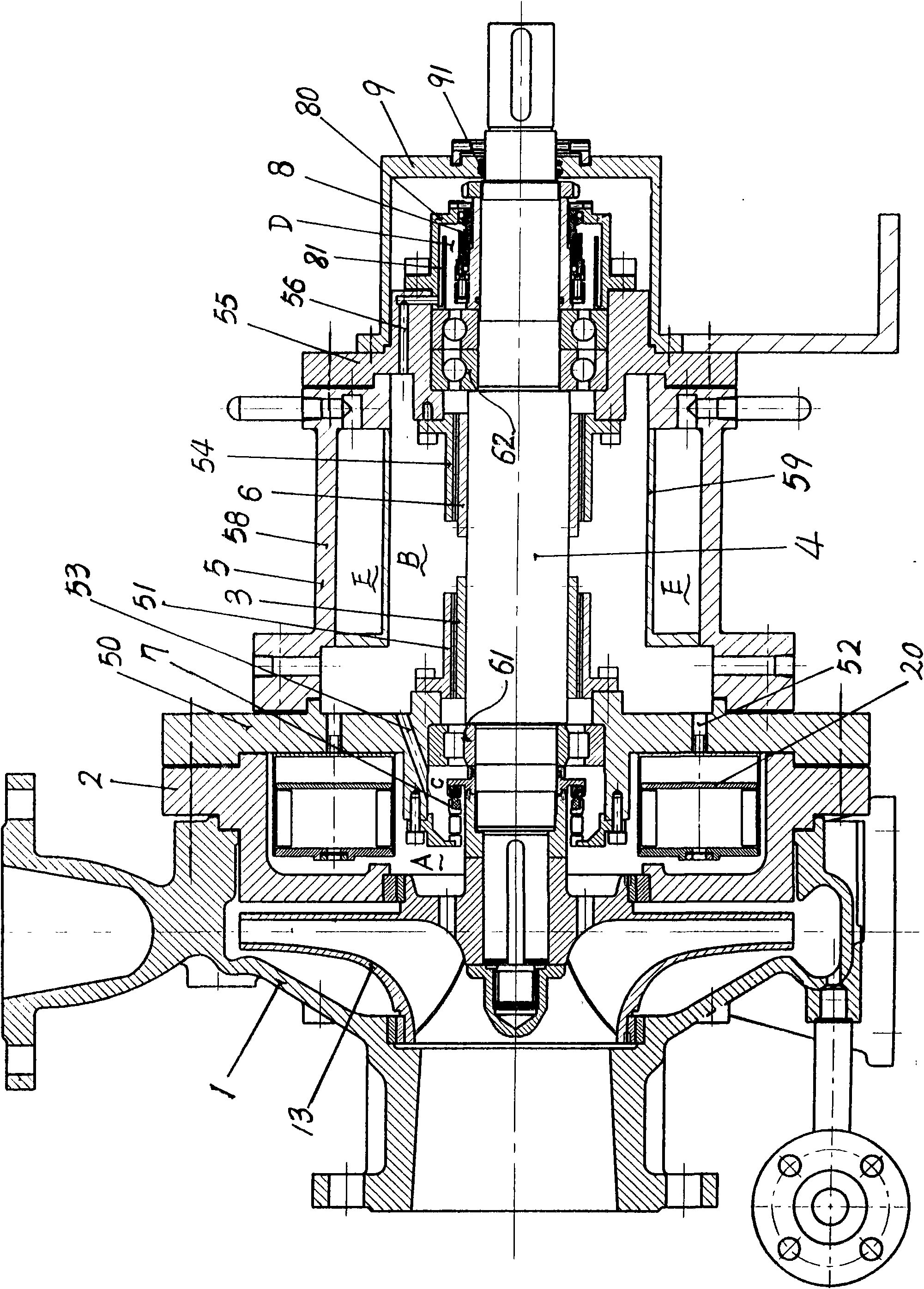
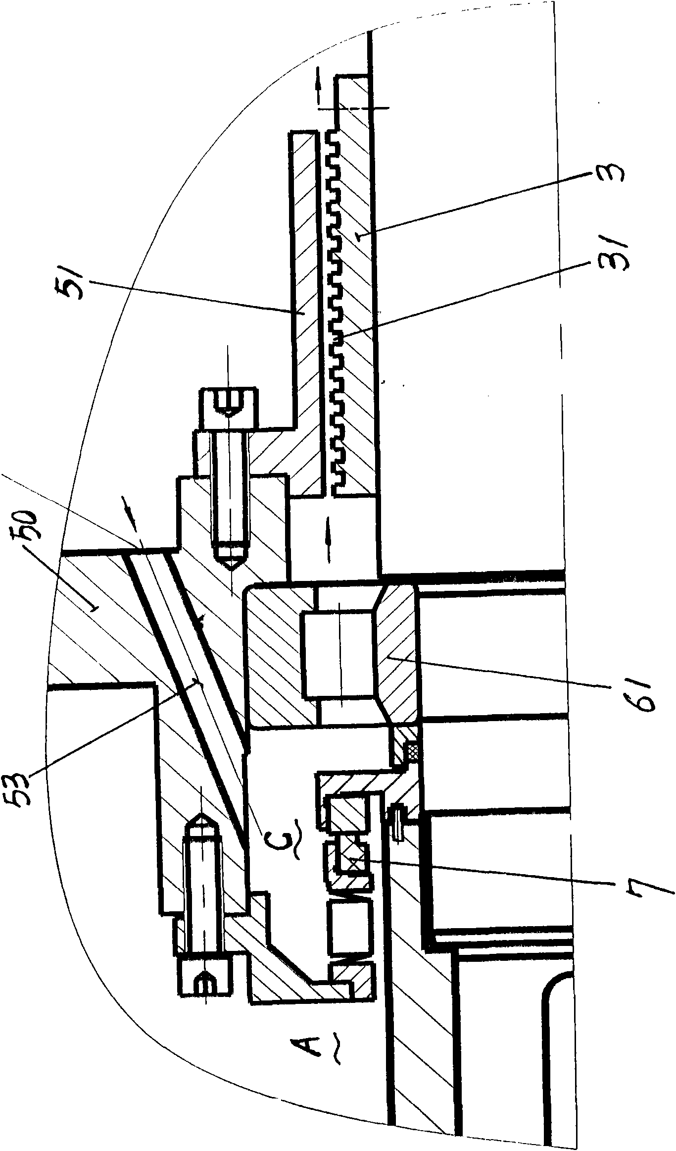
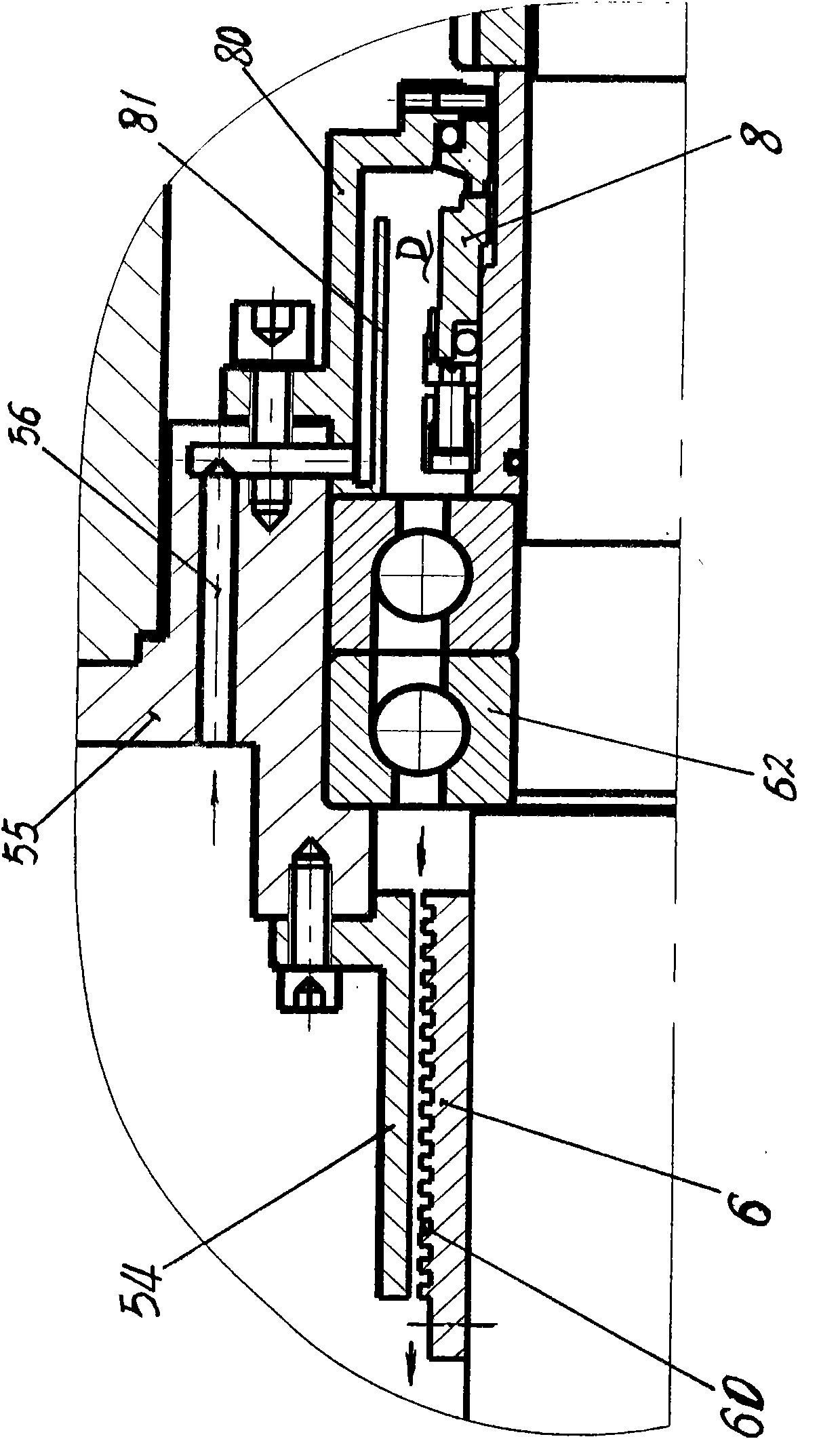
[0010] Shown in the embodiment of the accompanying drawings is a centrifugal pump. The present invention includes a pump body 1, an impeller 13, a pump cover 2, a pump shaft 4, and a bearing housing 5. The bearing housing 5 is composed of a front end plate 50, a cylinder body 58, and a rear end plate 55. The pump shaft 4 is connected with rolling bearings 61, 62 The front and rear end plates of the bearing box 5 are rotated and installed. In the inner cavity A of the pump cover 2, a mechanical seal device is provided between the front end plate 50 of the bearing box and the hub of the pump wheel or the pump shaft 4 ----- the front end mechanical seal device 7. There is another mechanical seal device between the rear end plate 55 of the bearing box and the pump shaft 4 - the rear end mechanical seal device 8, and the front and rear end mechanical seal devices 7 and 8 form the inner cavity B of the bearing box 5 The airtight inner cavity is filled with cooling lubricating oil in...


PUM


Abstract

The invention provides a high performance mechanical canned motor pump, which comprises a pump body (1), a pump cover (2), an impeller (13), a pump shaft (4), and a bearing box (5), and is characterized in that: a mechanical sealing device (7) is arranged between the front end of the bearing box (5) and an impeller hub or the pump shaft; a mechanical sealing device (8) is arranged between the rear end of the bearing box (5) and the pump shaft (4); a front end plate (50) of the bearing box (5) is provided with a pressure equalizer (20) to make the pressure of an inner cavity (B) of the bearing box and the inner cavity (A) of the pump cover (2) balanced; and screw pumping rings (3 and 6) and circumfluence holes (53 and 56) are arranged corresponding to the front and back mechanical sealing devices to fully cool and radiate the mechanical sealing devices and a rolling bearing. The high performance mechanical canned motor pump has the advantages of good leakproofness, long service life, safe and reliable use, good functionality and strong adaptive capacity, can be applicable to various working pressures, and fully meets the use requirement on places under working conditions such as high-pressure, toxic, flammable and explosive medium and the like.

Description

technical field [0001] The present invention relates to liquid transfer pumps, such as gear pumps, lobe pumps, centrifugal pumps, especially centrifugal pumps. Background technique [0002] Gear pumps, lobe pumps and centrifugal pumps are mainly composed of pump body, pump cover, pump wheel, pump shaft and bearing box. The bearing box is fixedly connected to the pump cover through the suspension at the front end. In order to prevent the medium from leaking from the pump shaft, There is a sealing device between the pump shaft and the pump cover, especially the mechanical sealing device. Due to the relatively high pressure in the pump cavity, or when the sealing effect is required to be high, the requirements for the mechanical sealing device are also very high. Once the sealing device fails, a large amount of medium will leak. For example, the double-end mechanical seal device improves the reliability of the seal, but the double-end mechanical seal device must be equipped wit...

Claims


Application Information

Patent Timeline
Patent Type & Authority Applications(China)
IPC IPC(8): F04D1/00F04D29/046F04D29/043F04D29/10
Inventor 臧克靖永毅杨德乾栾晓颖柴鹏举
Owner DANDONG COLOSSUS GROUP
Why Eureka
Try Eureka