Electrical contact element

a contact element and electric technology, applied in the direction of coupling contact parts, fastening/insulating connecting parts, electrical equipment, etc., can solve the problems of reducing unable to achieve the strength of the flat terminal pin in the direction of its free end, etc., and achieve the effect of increasing the stiffness of the retaining elemen

Active Publication Date: 2006-02-14
YAZAKI EURO
View PDF9 Cites 13 Cited by
  • Summary
  • Abstract
  • Description
  • Claims
  • Application Information

AI Technical Summary

Benefits of technology

[0021]As the retaining element is formed strip-like and is arranged in the base element, the outer dimensions of the contact element can be reduced, i.e. the box-like cross-section can be formed in total smaller. The base element is, preferably, punched from a sheet material and is bent into its shape. The retaining element provided for retaining the contact element, is still made from a steel, so that the necessary elastic characteristics are achieved and it provides, further, the necessary retainment security against withdrawal from a connector housing. By means of the smaller dimensions, the pattern dimensions, with which such miniaturized contact elements can be arranged, can be reduced compared to the embodiments according to the State of the Art. A further advantage is that also the area of the flat terminal pin is reinforced as a whole by the pin-reinforcement portion of the retaining element accommodated between the pin portions made from an electrical conductive material. The material, from which the retaining element is manufactured, has to have a higher strength than the material from which the base element is manufactured. But it has not to be manufactured necessarily from a spring steel, when the requirements are correspondingly.
[0022]Thus, during the repeated connecting and detaching of connectors, having a multitude of such contact elements, especially the danger, that one of the contact elements is bent, is significantly reduced. If the base element is made from a copper material, the danger of deforming the flat terminal pin with the dimensions existing in miniaturized contact elements is significantly reduced.
[0024]By means of this measurement it is achieved, that the spring stiffness of the retaining element is improved. The free elastic length of the retaining element is, thus, reduced. Preferably it is provided, that the retaining element is angled following the pin-reinforcement portion in the direction towards the upper wall and is again angled thereto in the area of the opening, so that the support edge of the retaining portion projects outwards beyond the upper wall.
[0026]Further it is provided, that the upper wall has a support tab projecting into the space delimited by this upper wall, the side walls and the bottom wall. Thus it is achieved, that when pulling the cable attached to the contact element a secure support is achieved, as the second angled portion can be supported in the angled area on the support tab, so that the danger does not exist, that the second portion used for the retainment can be deformed.
[0027]For increasing the stiffness of the retaining element, a bead is provided in the area of the intermediate portion and of the first angled portion.

Problems solved by technology

Furthermore, by means of the reinforcement no improvement of the strength of the flat terminal pin in the direction to its free end is achieved, as no support is given in this area.
The construction with a U-like base element and a box-like locking spring enclosing the same, has the disadvantage, that the dimensions in the cross-section are enlarged.

Method used


Image

  • Electrical contact element
  • Electrical contact element
  • Electrical contact element

Examples


Embodiment Construction

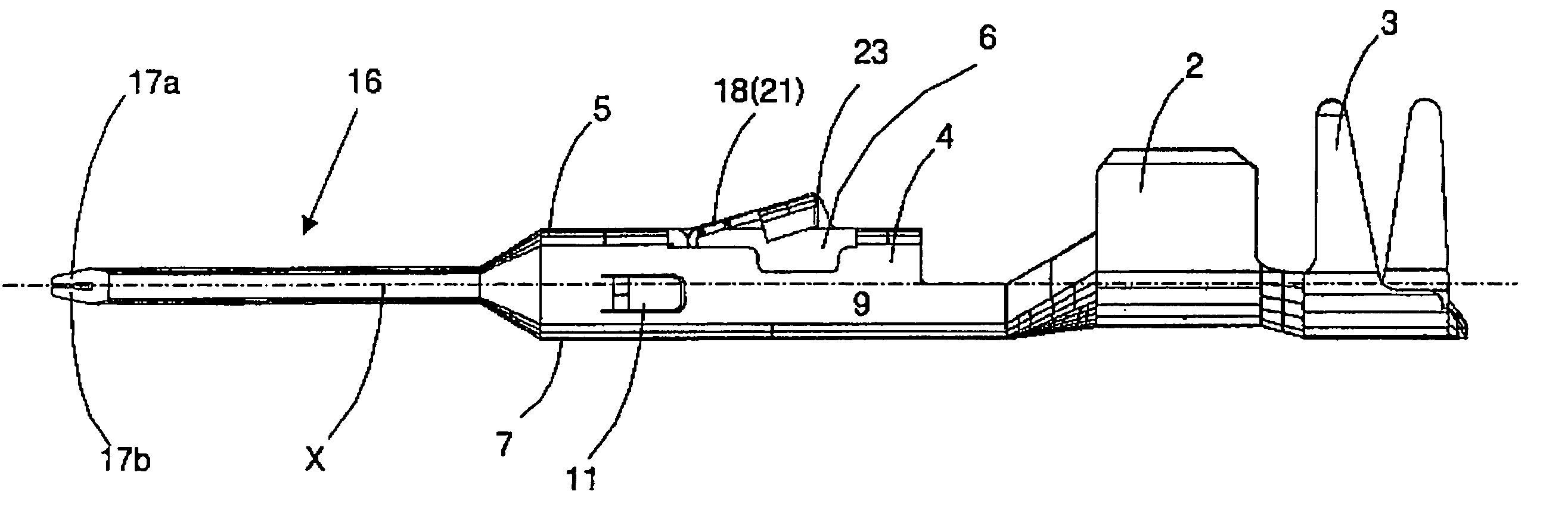
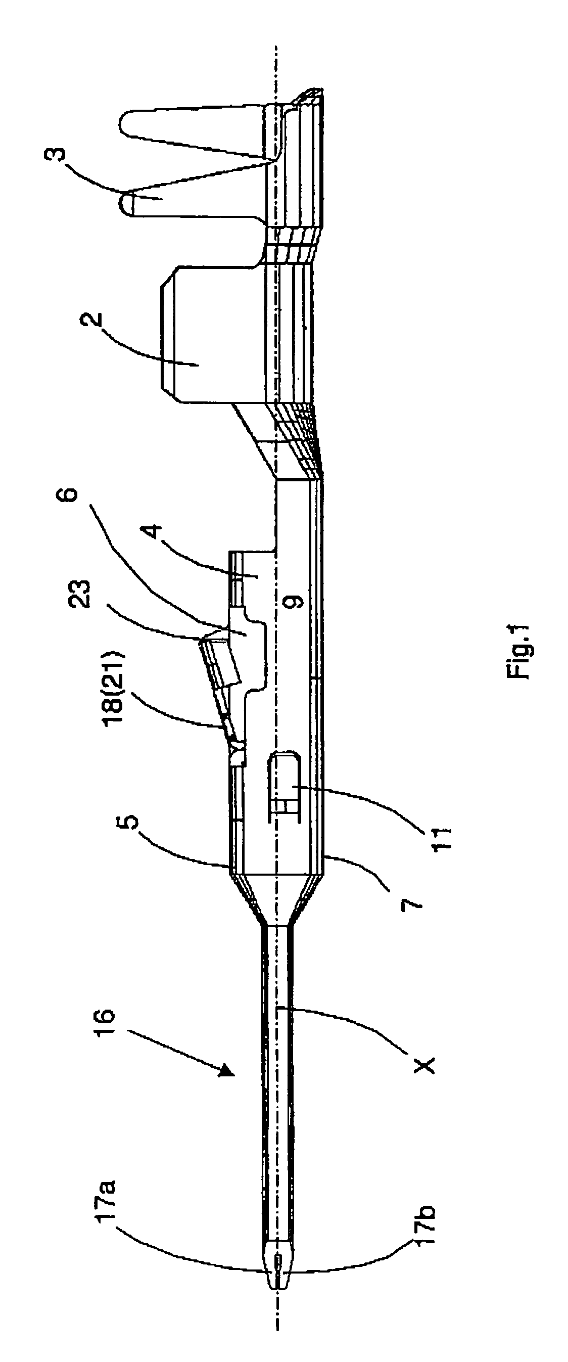
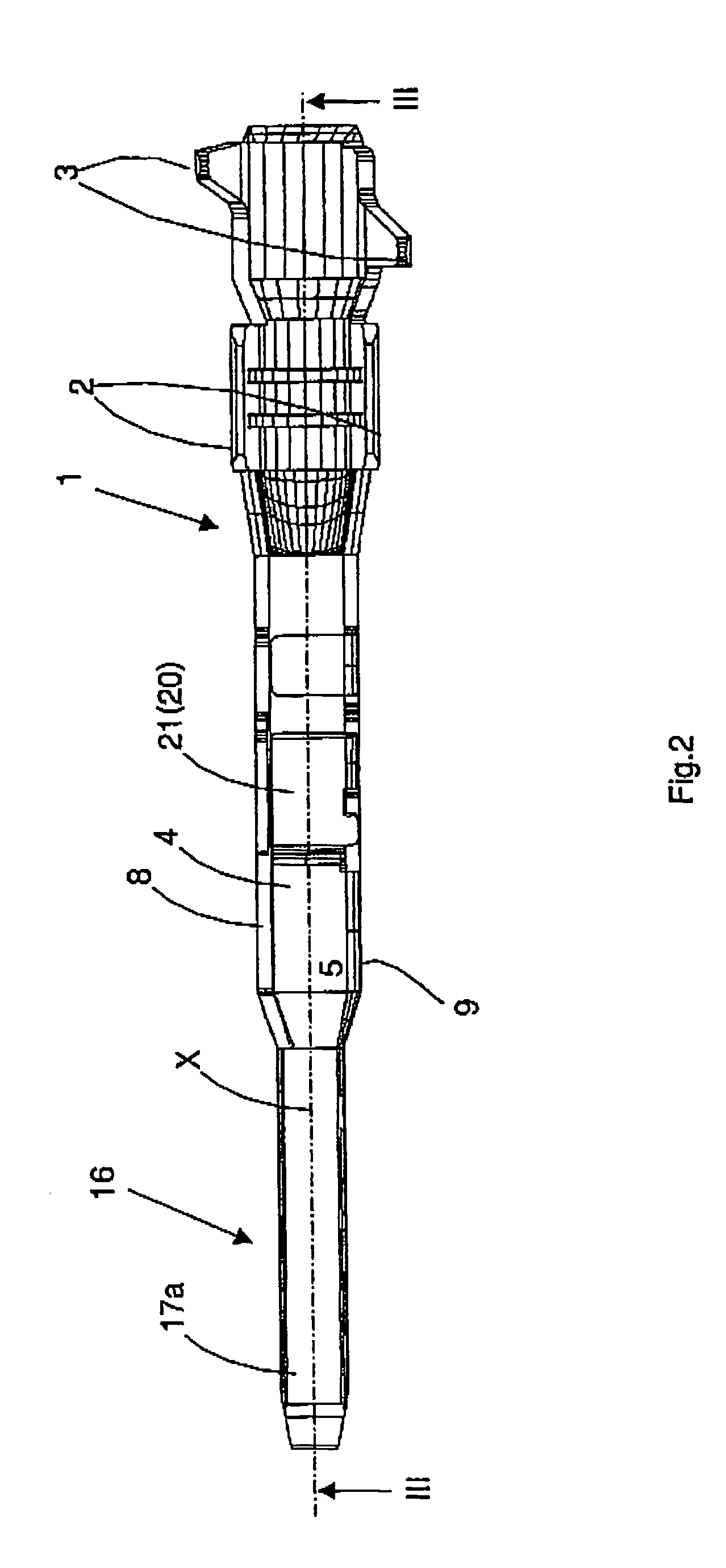
[0036]From FIGS. 1 to 4 an electrical contact element is visible, comprising a base element 1, formed from a copper material, especially a copper sheet by means of punching and bending. The base element 1 comprises a conductor contact portion 2 in form of two tabs and an insulation crimping portion 3, which also comprises two tabs. In this area, the base element 1 has essentially a U-like cross-section, which is especially visible from FIG. 4. In this portion an electrical cable (not shown) is received. More specifically, the two tabs of the conductor contact portion 2 are connected to the conductor of the cable by crimping. The two tabs of the insulation crimping portion 3 are crimped to the insulation of the cable, so that the cable is retained. The two conductor contact portions 2 serve to secure a sufficient electrically conductive contact between the base element 1 of the contact element and the conductor of the cable.

[0037]A base portion 4 follows the conductor contact portion...


PUM


Abstract

An electrical contact element including a base element (1) formed from a flat material with a high electrical conductivity and includes a conductor contact portion (2), a base portion (4) integrally connected to the conductor contact portion (2) and formed box-like defined by an upper wall (5) with an opening (6), a bottom wall (7) arranged opposite to the upper wall (5) and two side walls (8, 9) connecting the upper wall (5) and the bottom wall (7), and a flat terminal pin (16) integrally connected to the base portion (4) and extending away from the conductor contact portion (2) and having two vertically arranged pin portions (17a, 17b). The contact element also includes an elastic retaining element (18) formed from a sheet spring steel and including a flat pin-reinforcement portion (19) arranged between the two pin portions (17a, 17b), an intermediate portion (20) extending from the pin-reinforcement portion (19) and abutting an inner side of the bottom wall (7), and an elastic retaining portion (21) angled relative to the intermediate portion (20) and projecting out of the opening (6) and forming a support edge (23).

Description

BACKGROUND OF THE INVENTION[0001]The invention relates to an electrical contact element and, especially, such a contact element which has especially small dimensions and is provided with a flat terminal pin, which, for example, has a width of 1.2 mm and a thickness of in total 0.64 mm. Such electrical contact elements are, for example, used for connecting electrically operated components or electronic components in a vehicle.[0002]Several of such contact elements are accommodated in a housing of a connector. The housing has accommodation chambers, which are arranged next to each other or above each other, respectively, in a specific pattern and accommodate a contact element, respectively. In this case, the contact element has to be secured against withdrawal. The retainment has also to be able to take up the connection forces acting on the contact elements.[0003]EP 0 821 435 B1 (U.S. Pat. No. 5,989,079) describes an electrical contact element. This comprises a base element, made fro...

Claims


Application Information

Patent Timeline
Patent Type & Authority Patents(United States)
IPC IPC(8): H01R13/02H01R4/18H01R11/18H01R13/17H01R13/428
CPCH01R13/428H01R13/17H01R4/184
Inventor LUTSCH, HARALD MICHAELRESMAN, RANKOLEKIC, MARIOPOPOVIC, DEAN
Owner YAZAKI EURO
Why Eureka
Try Eureka