Rotary electric machine

a rotary electric machine and electric motor technology, applied in windings, dynamo-electric components, magnetic circuit shapes/forms/construction, etc., can solve the problems of increasing magnetic noise due to an increase in magnetic vibration, power output will decrease, etc., to improve the power output, the effect of reducing the temperature of the stator winding

Inactive Publication Date: 2006-02-14
DENSO CORP
View PDF14 Cites 34 Cited by
  • Summary
  • Abstract
  • Description
  • Claims
  • Application Information

AI Technical Summary

Benefits of technology

[0006]The present invention is made in view of the foregoing matter and it is an object of the present invention to provide a rotary electric machine capable of improving its power output in accordance with temperature decrease and reducing magnetic noise.
[0008]Since the width of the insertion portion is smaller than the distance between the first wall and the second wall of the slot, a gap is formed between the insertion portion and one of the first wall and the second wall. Therefore, it is easy to insert the insertion portion in the slot. Further, since the insertion portion makes contact with one of the first wall and the second wall, heat generated in the stator winding is transferred to the stator core. Therefore, temperature of the stator winding decreases. Accordingly, power output of the rotary electric machine improves. Also, vibrations of teeth reduce.

Problems solved by technology

As a result, it is likely that power output will decrease.
As a result, magnetic noise increases due to an increase in magnetic vibrations.

Method used


Image

  • Rotary electric machine
  • Rotary electric machine
  • Rotary electric machine

Examples


Embodiment Construction

[0015]The rotary electric machine of the present invention is for example applied to a three-phase vehicular alternator that is mounted and fixed on an engine and driven by the engine. An embodiment of the vehicular alternator in which the present invention is applied will be described in detail with reference to the drawings.

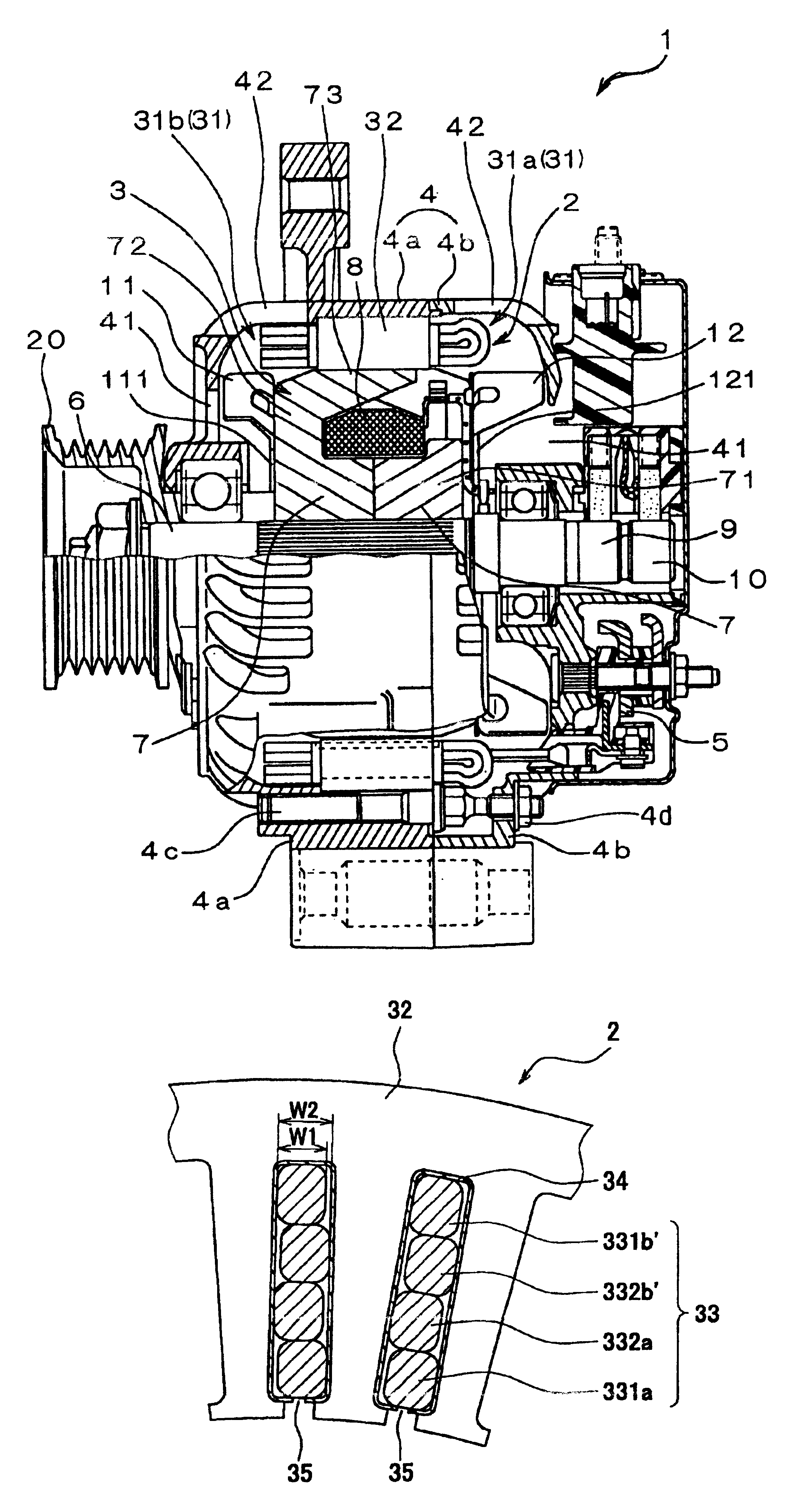
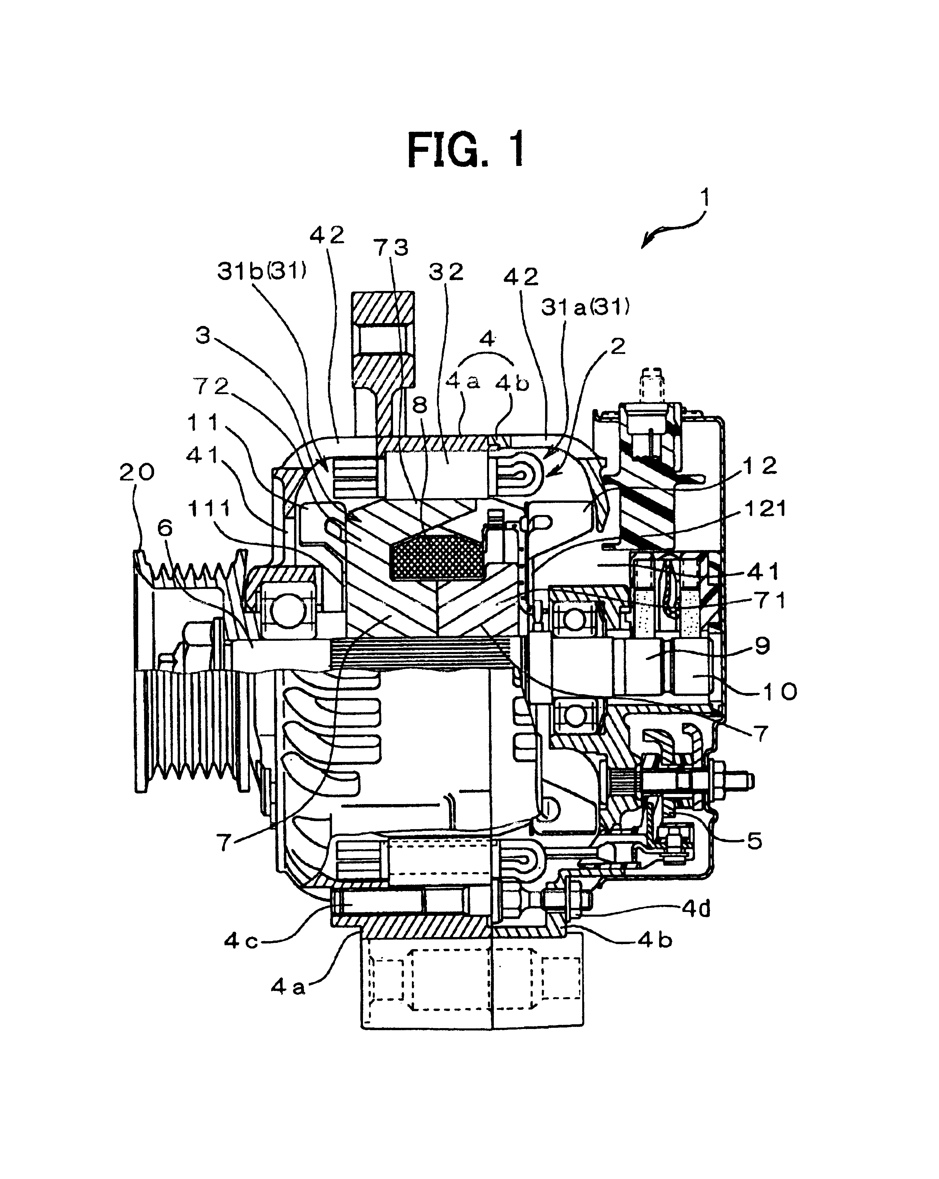
[0016]As shown in FIG. 1, the vehicular alternator 1 of the embodiment includes a stator 2 functioning as an armature, a rotor 3 functioning as a field magnet, a housing 4 having a front housing 4a and a rear housing 4b, and a rectifier 5. The front housing 4a and the rear housing 4b hold the stator 2 by a stud bolt 4c and rotatably support the rotor 3. The rectifier 5 rectifies an AC voltage output from the stator 2 to a DC voltage.

[0017]The rotor 3 rotates with a shaft 6. The rotor 3 includes a Lundell-type pole core 7, a field coil 8, slip rings 9, 10, a mixed flow fan 11, and a centrifugal fan 12 as air blowing devices. The shaft 6 is connected to a pulley ...


PUM


Abstract

In a vehicular alternator, a stator is arranged to oppose a rotor in a housing. The stator includes a stator core, which forms a plurality of slots extending in an axial direction of the stator core, and a stator winding wound around the stator core. The stator winding includes electric conductors held in the slots. Each of the electric conductors has a circumferential width that is smaller than a circumferential distance between a first wall and a second wall defining the slot. The first wall and the second wall oppose each other in a circumferential direction. The electric conductors are alternately in contact with one of the first wall and the second wall.

Description

CROSS REFERENCE TO RELATED APPLICATION[0001]This application is based on Japanese Patent Application No. 2002-202073 filed on Jul. 11, 2002, the disclosure of which is incorporated herein by reference.FIELD OF THE INVENTION[0002]The present invention relates to a rotary electric machine such as a vehicular alternator mounted on passenger vehicles or trucks.BACKGROUND OF THE INVENTION[0003]In a vehicular alternator disclosed in JP-B2-2927288 (U.S. Pat. No. 5,998,903), a winding of a stator is constructed of a plurality of U-shaped conductor segments. The U-shaped conductor segments are inserted in slots of a stator core from an axial end of the stator core. Ends of the U-shaped conductor segments are connected at an opposite axial end of the stator core.[0004]In this kind of stator core, small gaps are required between the conductor segments and inside walls defining the slots to reduce resistance therebetween at the time of installation of the conductor segments. However, if the con...

Claims


Application Information

Patent Timeline
Patent Type & Authority Patents(United States)
IPC IPC(8): H02K23/02H02K3/14H02K19/22H02K1/16H02K3/12H02K3/28
CPCH02K3/12H02K1/16H02K3/14
Inventor WADA, HITOSHIISHIKAWA, HIROAKIISHIDA, HIROSHI
Owner DENSO CORP
Why Eureka
Try Eureka