System for reducing leakage in integrated circuits during sleep mode

a technology of integrated circuits and leakage reduction, applied in the field of integrated circuits, can solve the problems of hvt's relatively slow turn on, current leakage is particularly problematic, and latches primarily employing hvts, so as to minimize leakage, minimize leakage, and present invention

Inactive Publication Date: 2006-02-14
QUALCOMM INC
View PDF7 Cites 25 Cited by
  • Summary
  • Abstract
  • Description
  • Claims
  • Application Information

AI Technical Summary

Benefits of technology

[0019]The novel design of the present invention is facilitated by the feedback from the output of the second circuit component to the input of the first circuit component when the associated latch or other circuit is in sleep mode. This minimizes leakage during sleep mode without compromising the performance of the accompanying latch. Minimizing leakage during sleep mode by strategically feeding back slave half-latch data to the master cell when the latch is in sleep mode eliminates conventional tradeoffs between low leakage and high performance and between setup time and transition delay. The present invention enables low-leakage latches without compromising performance and enables short setup times without compromising transition delay and visa versa. Furthermore, the clock may either sleep high or low without compromising leakage or performance characteristics. This increases the versatility, performance, and leakage characteristics of latches incorporating the system for reducing leakage of the present invention.

Problems solved by technology

Current leakage is particularly problematic in mobile applications, such as cellular telephones, laptops, and personal digital assistants, where long battery life is desirable.
Unfortunately, HVT's turn on relatively slowly.
Consequently, latches employing primarily HVT's exhibit good leakage characteristics but are typically slow, which reduces the performance of the entire synchronous digital system.
However, LVT's are often leaky.
Consequently, latches and associated systems employing LVT's are often leaky.
A tradeoff exists between low leakage and high performance.
Generally, high performance latches exhibit high current leakage during sleep mode.
Unfortunately, to achieve acceptable performance and leakage characteristics, these hybrid latches require that the synchronizing clock sleeps low such that clock is low when the latch is in sleep mode or that the synchronizing clock sleeps high such that the clock is high when the latch is in sleep mode.
The resulting latch exhibits an undesirably lengthy setup time and a short transition delay.
The lengthy setup time results from the slow HVT pass gate.
The clock signal that controls the LVT pass gate must wait for the input to arrive at the LVT pass gate via the slow HVT pass gate, yielding a long setup time.
The resulting latch exhibits a short setup time and an undesirably lengthy transition delay.
The short setup time results from the fast LVT pass gate.
The lengthy transition delay results from the slow HVT pass gate.
Conventionally, a tradeoff exists between setup time and transition delay.
Conventional hybrid latches require that the clock either sleep high or low, causing a lengthy setup time or transition delay, respectively.
Furthermore, the requirement that the clock either sleep high or low limits the applicability of these latches to certain applications not requiring latches to selectively sleep high and / or low.

Method used


Image

  • System for reducing leakage in integrated circuits during sleep mode
  • System for reducing leakage in integrated circuits during sleep mode
  • System for reducing leakage in integrated circuits during sleep mode

Examples


Embodiment Construction

[0027]While the present invention is described herein with reference to illustrative embodiments for particular applications, it should be understood that the invention is not limited thereto. Those having ordinary skill in the art and access to the teachings provided herein will recognize additional modifications, applications, and embodiments within the scope thereof and additional fields in which the present invention would be of significant utility.

[0028]The following discussion of a conventional master-slave D flip-flop latch is intended to facilitate an understanding of the present invention.

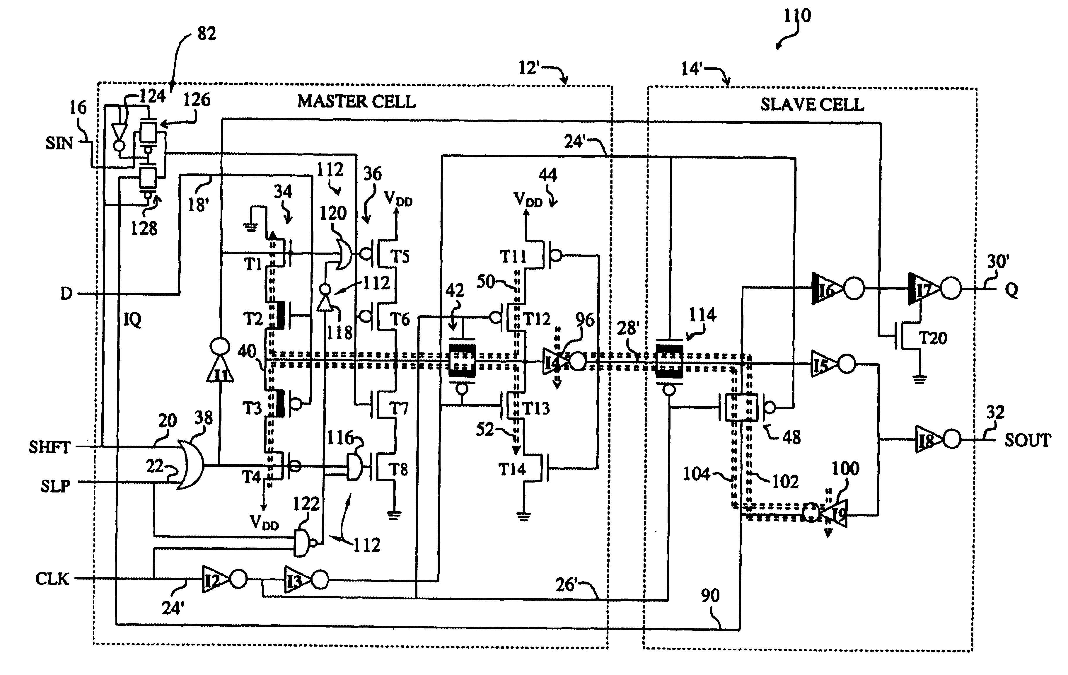
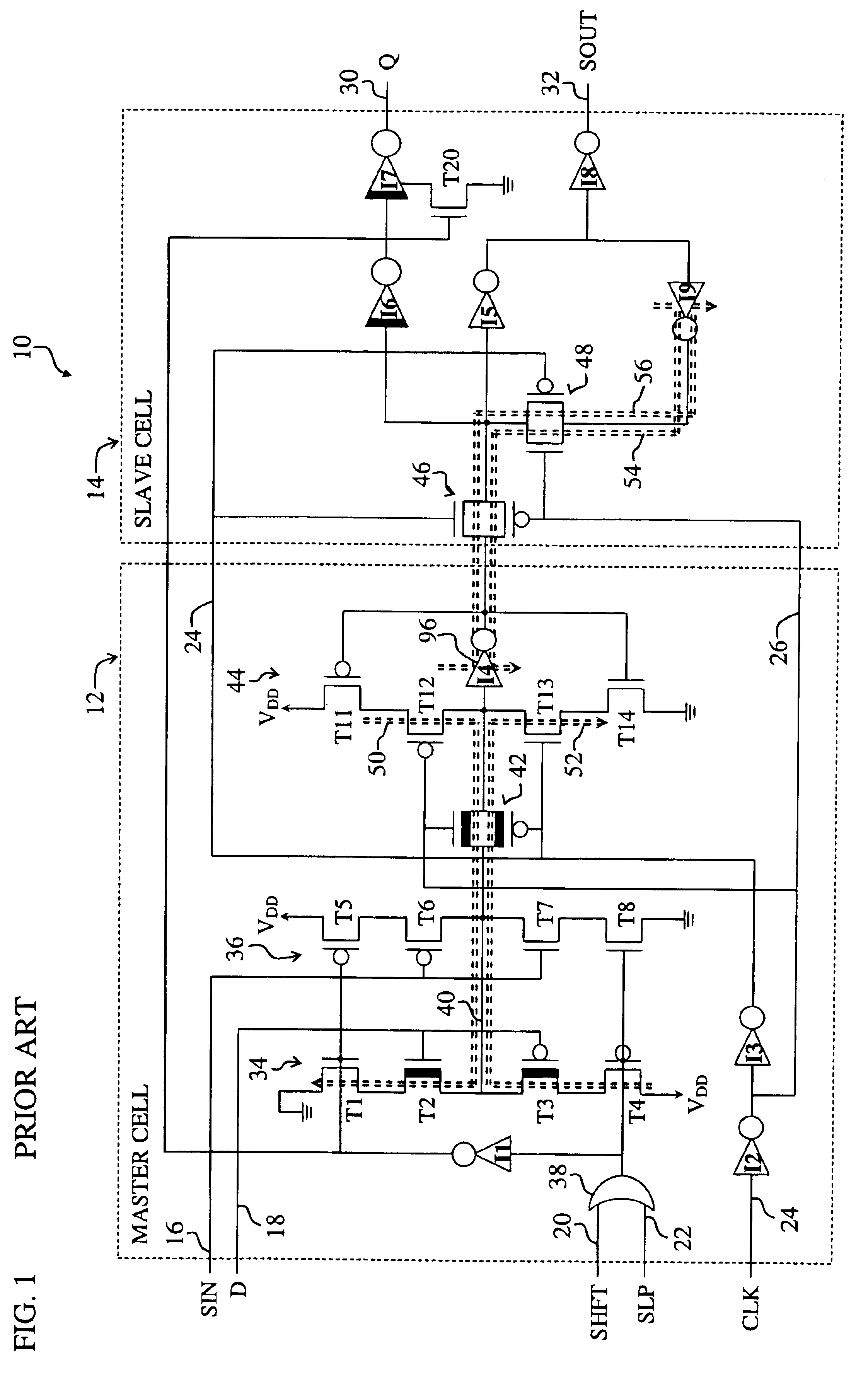
[0029]FIG. 1 is a diagram of a conventional master-slave D flip-flop latch 10 requiring that the clock must sleep low. For clarity, various well-known components, such as power supplies, substrates, and so on, have been omitted from the figures, however those skilled in the art with access to the present teachings will know which components to implement and how to implement them to meet th...


PUM


Abstract

A system for reducing current leakage in an integrated circuit. The system includes a first circuit component and a second circuit component in a path between a high voltage state and a low voltage state, such as ground. A feedback mechanism selectively provides feedback from an output of the second circuit component to an input of the first circuit component to selectively cutoff the path at the first circuit when the path is not cutoff at the second circuit. In a more specific embodiment, feedback mechanism preserves data in the integrated circuit via a multiplexer that selectively enables the feedback when the integrated circuit is in sleep mode. The first and second circuit components are High Voltage Threshold (HVT) CMOS inverters. The feedback path is chosen so that when the feedback path is activated, leakage paths through the CMOS inverters are cutoff.

Description

RELATED APPLICATIONS[0001]This application claims priority to U.S. Provisional Application No. 60 / 422,367, filed on Oct. 29, 2002.BACKGROUND OF THE INVENTION[0002]1. Field of Invention[0003]This invention relates to integrated circuits. Specifically, the present invention relates to systems for preventing or reducing leakage in synchronous digital systems during sleep mode.[0004]2. Description of the Related Art[0005]Integrated circuits are employed in various demanding applications including personal computers, cellular telephones, watches, and finite state machines. Such applications demand high-performance integrated circuits that exhibit minimal current leakage when idle or in sleep mode. Current leakage is particularly problematic in mobile applications, such as cellular telephones, laptops, and personal digital assistants, where long battery life is desirable.[0006]These applications often employ synchronous digital systems implemented via integrated circuits. Synchronous digi...

Claims


Application Information

Patent Timeline
Patent Type & Authority Patents(United States)
IPC IPC(8): G05F1/10H03K19/00
CPCH03K19/0016
Inventor UVIEGHARA, GREGORY A.
Owner QUALCOMM INC
Why Eureka
Try Eureka