Flexible solid state lighting strip

a solid-state lighting and flexible technology, applied in semiconductor devices for light sources, printed circuit non-printed electric components association, light and heating apparatus, etc., can solve problems such as running the risk of ruining copper tracks, and achieve the effect of ensuring performance and not compromising performan

Active Publication Date: 2019-04-18
SIGNIFY HLDG BV
View PDF0 Cites 0 Cited by
  • Summary
  • Abstract
  • Description
  • Claims
  • Application Information

AI Technical Summary

Benefits of technology

[0004]It is an object of the present invention to provide an improved flexible solid state lighting strip. It is a particular object of the present invention to provide a flexible solid state lighting strip which allows curving in at least in two (orthogonal) directions, without compromising its performance.
[0007]Due to the elongate circuit board being bent into sections about folding lines which are parallel to the board's longitudinal axis such that longitudinally subsequent sections are oriented at least 45 degrees, preferably (approximately) 90 degrees, apart, the strip is flexible in two directions. This in turn makes the strip easier to mount in various applications.
[0018]The at least one solid state light source may be positioned offset from a longitudinal mid of the sections of the elongate circuit board. As the at least one solid state light source typically is rigid, this placement may reduce the risk of damaging the solid state light source when the strip is flexed, since any bending of the sections when the strip is flexed is most likely to occur at the longitudinal mid of the respective section. Sections of the elongate circuit board may for example comprise two solid state light sources, one on each side of said longitudinal mid.
[0020]At least one hole may extend through the encapsulating material but not through the elongate circuit board. The at least one hole may be used to fixate the strip to some external structure, without using tape, glue or the like. Since the at least one hole does not pass through the elongate circuit board, a higher current can be used. The at least one hole also makes the strip easier to flex, i.e. make it more flexible. The at least one hole can conveniently be positioned at the aforementioned second and third sections, which keeps the strip smaller compared to other fixation solutions.

Problems solved by technology

However, perpendicular to this direction one cannot bend the strip without running the risk of ruining the copper tracks.

Method used


Image

  • Flexible solid state lighting strip
  • Flexible solid state lighting strip
  • Flexible solid state lighting strip

Examples


Embodiment Construction

[0034]The present invention will now be described more fully hereinafter with reference to the accompanying drawings, in which currently preferred embodiments of the invention are shown. This invention may, however, be embodied in many different forms and should not be construed as limited to the embodiments set forth herein; rather, these embodiments are provided for thoroughness and completeness, and fully convey the scope of the invention to the skilled person.

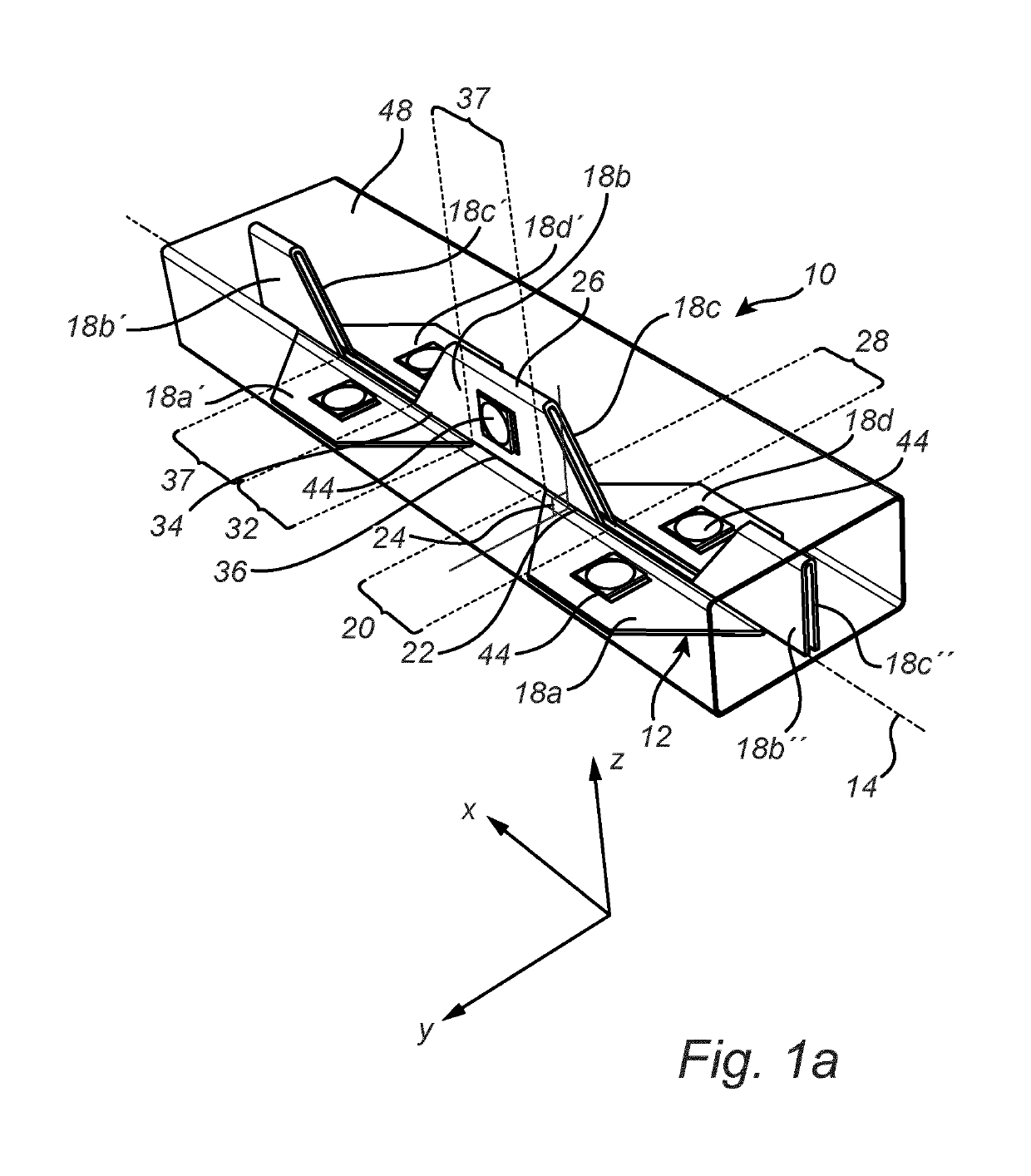
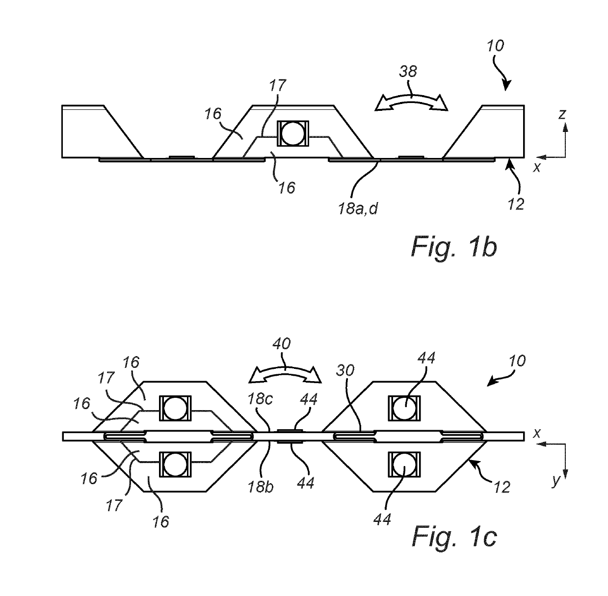
[0035]FIGS. 1a-c show a flexible solid state lighting strip 10 according to an embodiment of the present invention. For reference, a three dimensional Cartesian coordinate system with axis lines x, y and z is also shown.

[0036]The strip 10 comprises an elongate circuit board 12. The elongate circuit board 12 has a longitudinal axis 14 (x direction). The elongate circuit board 12 comprises a non-conductive substrate and electrically conductive metal tracks 16. The non-conductive substrate can for example be at least one foil ...


PUM


Abstract

The present invention relates to a flexible solid state lighting strip (10), comprising: an elongate circuit board (12) having a longitudinal axis (14), wherein the elongate circuit board is bent, about folding lines (22; 26; 30; 34) parallel to the longitudinal axis of the elongate circuit board, into sections (18), such that subsequent sections along the longitudinal axis are oriented at least 45 degrees, preferably (approximately) 90 degrees, apart; and at least one solid state light source (44) mounted on the elongate circuit board.

Description

FIELD OF THE INVENTION[0001]The present intention relates to a flexible solid state lighting strip, such as a flexible LED (light emitting diode) strip.BACKGROUND OF THE INVENTION[0002]Present LED strips can be bent easily in one direction, see for example the stepwise curved lamp unit in FIGS. 1 and 2 of US 2011 / 0228536 (Im et al.). However, perpendicular to this direction one cannot bend the strip without running the risk of ruining the copper tracks. So, installing the strip goes well as long as the strip has to curve in one direction only.[0003]In US 2015 / 0354797 a flexible circuit board is disclosed for an illumination device. The flexible circuit board includes a plurality of mounting sections for the LEDs and connection sections for mutual connecting adjacent mounting sections, so forming a longitudinal lighting device. The connection sections forming a predetermined angle in the longitudinal direction with respect to the mounting sections.SUMMARY OF THE INVENTION[0004]It is ...

Claims


Application Information

Patent Timeline
Patent Type & Authority Applications(United States)
IPC IPC(8): F21S4/22F21V23/00H05K1/02H05K1/18H05K1/11
CPCF21S4/22F21V23/005H05K1/028H05K1/189H05K1/118F21Y2115/10H05K2201/10106H05K3/284H05K2201/055F21S4/26F21Y2107/70
Inventor BUKKEMS, PETER JOHANNES MARTINUSANSEMS, JOHANNES PETRUS MARIABERGMAN, ANTHONIE HENDRIKVISSENBERG, MICHEL CORNELIS JOSEPHUS MARIEVAN STIJN, PATRICK HENRICUS JOHANNES
Owner SIGNIFY HLDG BV
Why Eureka
Try Eureka