Gas content measuring apparatus and method

a technology of gas content and measuring apparatus, applied in the direction of measuring devices, material analysis through optical means, instruments, etc., can solve the problems of reflection back to the light source, measurement error caused by coherent light signal reflection, and variation in intensity

Active Publication Date: 2008-07-29
OYJ VAISALA +1
View PDF15 Cites 6 Cited by
  • Summary
  • Abstract
  • Description
  • Claims
  • Application Information

AI Technical Summary

Benefits of technology

[0006]The invention is intended to eliminate the defects of the prior art disclosed above and for this purpose create a new type of apparatus and a significantly improved method for measuring a gas content.

Problems solved by technology

One source of measurement error is the errors caused by reflections of the coherent light signal.
The reflections form diffused light, leading to variations in intensity that—particularly in the form of the interference phenomenon—disturb measurement.
Reflections back to the light source are also a source of measurement error.

Method used


Image

  • Gas content measuring apparatus and method
  • Gas content measuring apparatus and method

Examples


Embodiment Construction

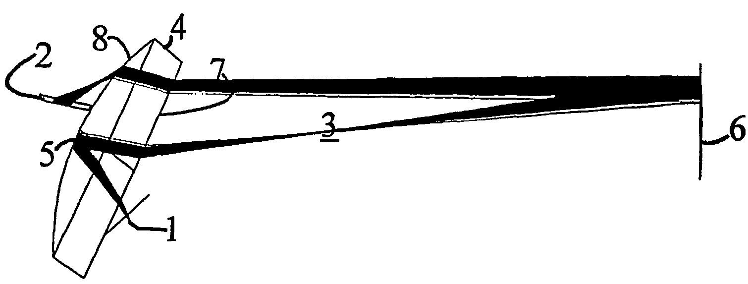
[0018]The measuring environment according to the invention utilizes a coherent light source 1, the attenuation in the measuring channel of the light from which is monitored in the vicinity of the absorption maximum or minimum of the desired gas. The narrow spectral band of the coherent light source 1 facilitates separating the measuring signal from background light. The attenuation in the measuring channel caused by the gas being measured is thus measured in a narrow band at the spectral peak specific to the gas. The narrowness characteristic of the band can be implemented by using either a light source with a narrow band or a separate narrow-band filter located in connection with the detector, or by a combination of both.

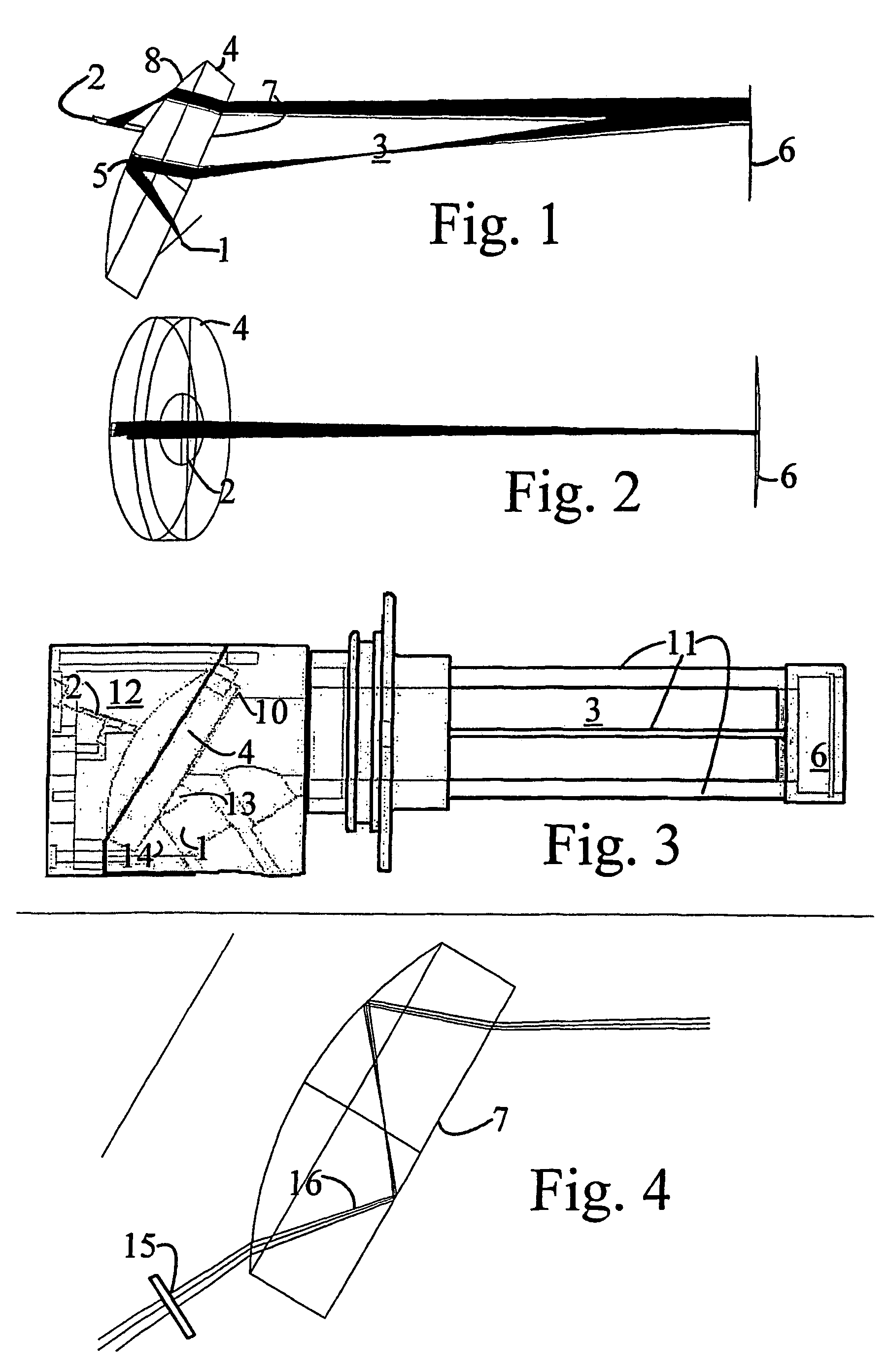
[0019]According to FIG. 1, the central components of the measuring apparatus according to the invention are a plane-convex lens 4, on the plane surface of which a coherent light source 1 is located. The light source aligns its beam obliquely to the plane surface 7 ...


PUM

PropertyMeasurementUnit
angleaaaaaaaaaa
angleaaaaaaaaaa
angle of incidenceaaaaaaaaaa

Abstract

This publication discloses an apparatus and method for measuring a gas content. The apparatus includes a light transmitter (1), by means of which coherent light can be sent to the measurement object (3), a receiver (2), by means of which light that has passed through the measurement object (3) can be detected, and optical means (4, 5, 6), by means of which the light intensity of the light transmitter (1) can be aimed at the receiver (2). According to the invention, the optical means include a lens element (4), the optical axis of which is arranged essentially obliquely relative to the longitudinal axis of the measurement object (3), so that the angles of the normals of the optical boundaries relative to the measuring signal are set obliquely. The lens element (4) is both a refracting and a reflecting element, and separates the measurement object (3) from the means (1, 2, 5).

Description

BACKGROUND OF THE INVENTION[0001]The present invention relates to a gas content measuring apparatus, according to the preamble of claim 1.[0002]The invention also relates to a measuring method.[0003]Measuring apparatuses of this kind are used, for example, to measure oxygen content.[0004]According to the prior art, measuring arrangements have been implemented, in which a coherent element is used as the light source and the path of the light is arranged, with the aid of a mirror, to travel twice through the measuring chamber. Using this arrangement brings all of the measurement electronics to the same side of the measurement channel. In solutions according to the prior art, achieving adequate measurement accuracy requires the creation of a relatively long measurement channel.[0005]One source of measurement error is the errors caused by reflections of the coherent light signal. The reflections form diffused light, leading to variations in intensity that—particularly in the form of the...

Claims


Application Information

Patent Timeline
Patent Type & Authority Patents(United States)
IPC IPC(8): G01N21/00G01NG01N21/09G01N21/25
CPCG01N21/09G01N21/3504G01N2201/064G01N2201/0636G01N2201/0638G01N2021/0396
Inventor KERANEN, REINO
Owner OYJ VAISALA
Why Eureka
Try Eureka