Micromirror modulation method and digital apparatus with improved grayscale

a micromirror and modulation method technology, applied in the field of image display techniques and micromirrorbased displays, can solve the problems of undesirable contrast ratio degradation, mirrors that switch arbitrarily fast, and difficult to create displays with high contras

Active Publication Date: 2006-02-14
TEXAS INSTR INC +1
View PDF13 Cites 42 Cited by
  • Summary
  • Abstract
  • Description
  • Claims
  • Application Information

AI Technical Summary

Benefits of technology

[0018]First, high contrast is achieved since the minimum amount of light that can be projected during a frame time is less than that projected during one time slot in a digital projection scheme.
[0019]Second, efficient use is made of light intensity data that arrive at the micromirror controller at a limited data rate. The combined analog and digital algorithms in the controller provide more different light levels at low intensities than are possible using only a digital algorithm.

Problems solved by technology

Creating a display with high contrast is challenging from an engineering standpoint since human perception of brightness is nonlinear.
However, this would require mirrors that switch arbitrarily fast.
Also, improper timing of control pulses “can lead to undesirable contrast ratio degradation” if the micromirror either switches unintentionally or follows an undesired trajectory, ibid.

Method used


Image

  • Micromirror modulation method and digital apparatus with improved grayscale
  • Micromirror modulation method and digital apparatus with improved grayscale
  • Micromirror modulation method and digital apparatus with improved grayscale

Examples


Embodiment Construction

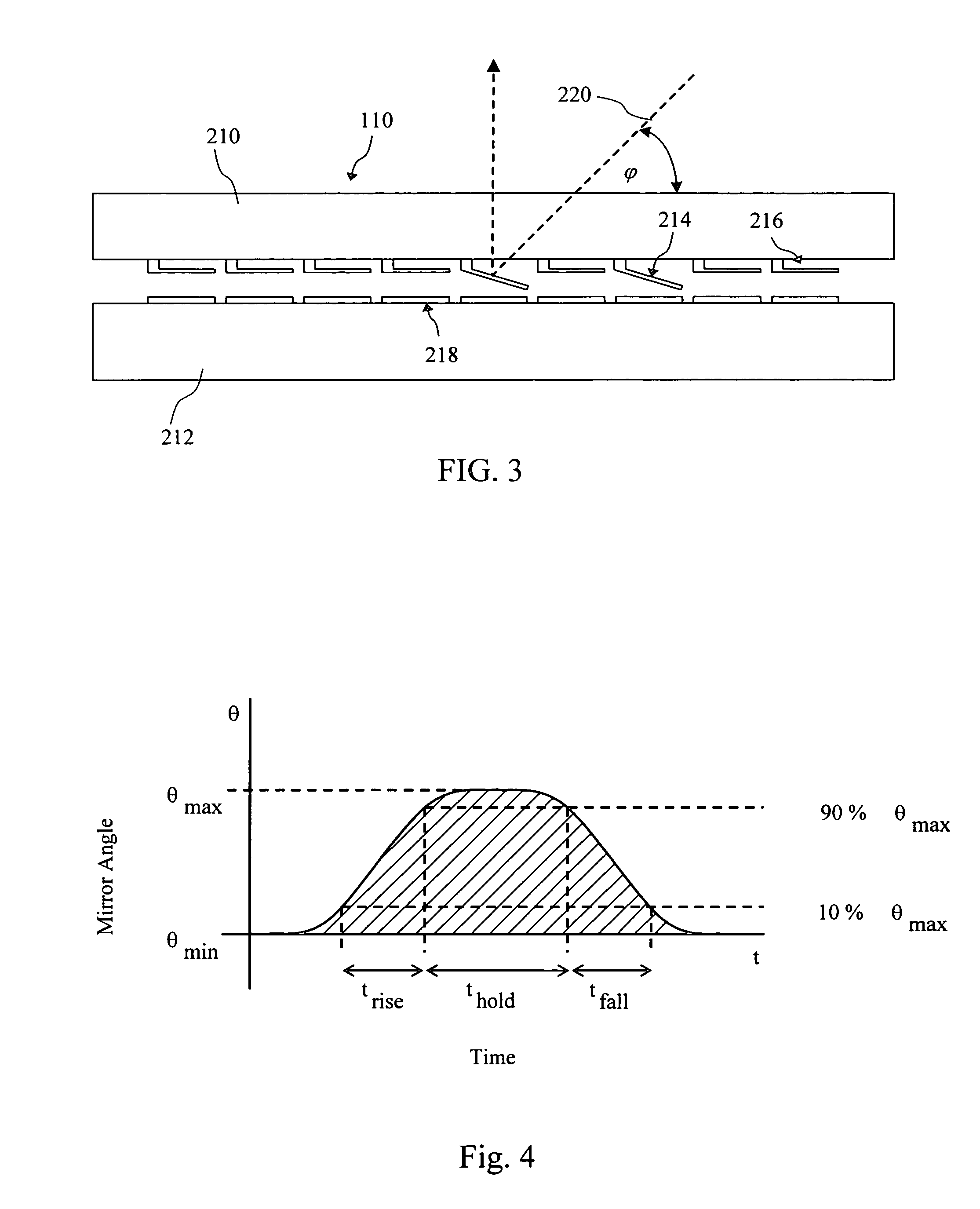
[0032]Processes for micro-fabricating a microelectromechanical system (MEMS) device such as a micromirror and micromirror array are disclosed in U.S. Pat. Nos. 5,835,256 and 6,046,840 both to Huibers, the subject matter of each being incorporated herein by reference.

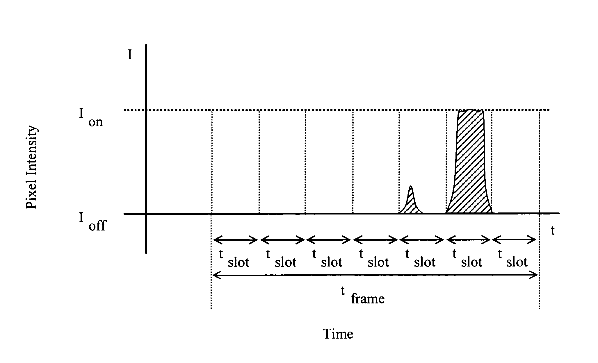
[0033]The present invention provides a method and an apparatus for achieving high contrast with a micromirror-based video display. The distinguishing feature of the invention is that the range of gray levels normally available from a digital micromirror display is extended by employing analog techniques and analog devices. The ability to display more different light levels leads to improved contrast and a more faithful, pleasing display.

[0034]The invention provides a method for combining analog and digital control of micromirror displays and a micromirror design that is compatible with the hybrid analog-digital control scheme. Gray levels for relatively bright pixels are produced using conventional digital modulation tec...


PUM


Abstract

A method and apparatus are disclosed for increasing contrast in micromirror-based image display devices. As a result the displayed image is a more faithful reproduction of the original and is more pleasing to human perception than is possible with a low contrast display. The method and apparatus comprise a micromirror design and a modulation scheme for driving micromirrors with a combination of analog and digital techniques to achieve partial and full micromirror deflection. The analog techniques permit the mirrors to be deflected to positions intermediate between the resting position and the position of maximum deflection. These intermediate deflections appear as intermediate light levels in an image. Compared to digital modulation, the analog techniques provide an increase in the number of light levels that can be displayed by a system that is limited by its incoming data rate and maximum micromirror speed.

Description

TECHNICAL FIELD OF THE INVENTION[0001]The present invention is related generally to image display techniques and micromirror-based displays.BACKGROUND OF THE INVENTION[0002]As market demands increase for display systems showing high quality images, micromirrors and micromirror arrays have blossomed in display applications.[0003]A common parameter in the evaluation and characterization of display systems is contrast. Contrast is defined as the ratio between the brightest and dimmest intensity that a display is capable of rendering in an image. Hence, a display that shows parts of an image as bright white while other areas of the same image are dark black has more contrast than a display which shows the same image in intermediate gray tones.[0004]Creating a display with high contrast is challenging from an engineering standpoint since human perception of brightness is nonlinear. Humans resolve brightness differences between dim objects more precisely than between bright objects. Hence...

Claims


Application Information

Patent Timeline
Patent Type & Authority Patents(United States)
IPC IPC(8): G02B26/00
CPCG02B26/0841H04N9/3182H04N9/312
Inventor HUIBERS, ANDREW
Owner TEXAS INSTR INC
Why Eureka
Try Eureka