Communication structure for multiplexed links

Inactive Publication Date: 2006-02-14
SAMSUNG ELECTRONICS CO LTD
View PDF19 Cites 87 Cited by
  • Summary
  • Abstract
  • Description
  • Claims
  • Application Information

AI Technical Summary

Benefits of technology

[0011]It is an object of the present invention to provide a novel communication structure and metho

Problems solved by technology

However, it has proven difficult and/or costly to create a communication system which can meet both the connection-like requirements of VoIP (voice data requiring a moderate data rate and having some tolerance for errors, but requiring low latency) and connectionless requirements of pure data (often utilizing a high, bursty data rate and having a relatively high tolerance to latency but little tolerance for errors).
However, support for RSVP must explicitly be implemented within an application and at each switch and/or router involved in the virtual connection, which has been difficult to achieve to date.
Further, there is a significant amount of time and overhead required to set up an RSVP connection which can negate the benefits of an RSVP connection for connections of relatively short duration.
Even when implemented, RSVP does not typically result in an efficient usage of network capacity as the maximum anticipated bandwidth and/or network capacity requirements must be reserved for the duration of the connection, even if they are not used, or are not used continuously.
Thus, in many circumstances, reserved network resources are sitting idle, or are under utilized, for some portion of time.
Further, RSVP does not include any incentive mechanism by which applications/us

Method used


Image

  • Communication structure for multiplexed links
  • Communication structure for multiplexed links
  • Communication structure for multiplexed links

Examples


Embodiment Construction

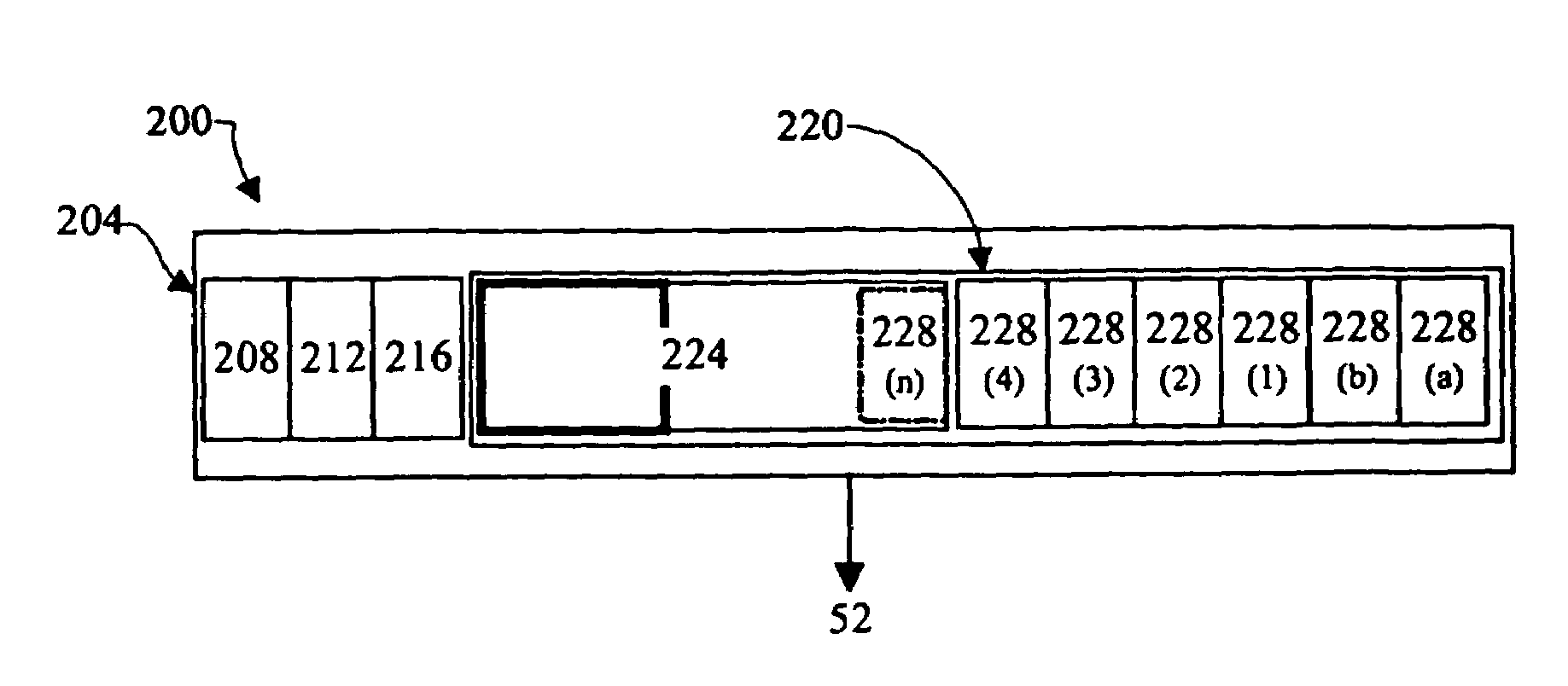
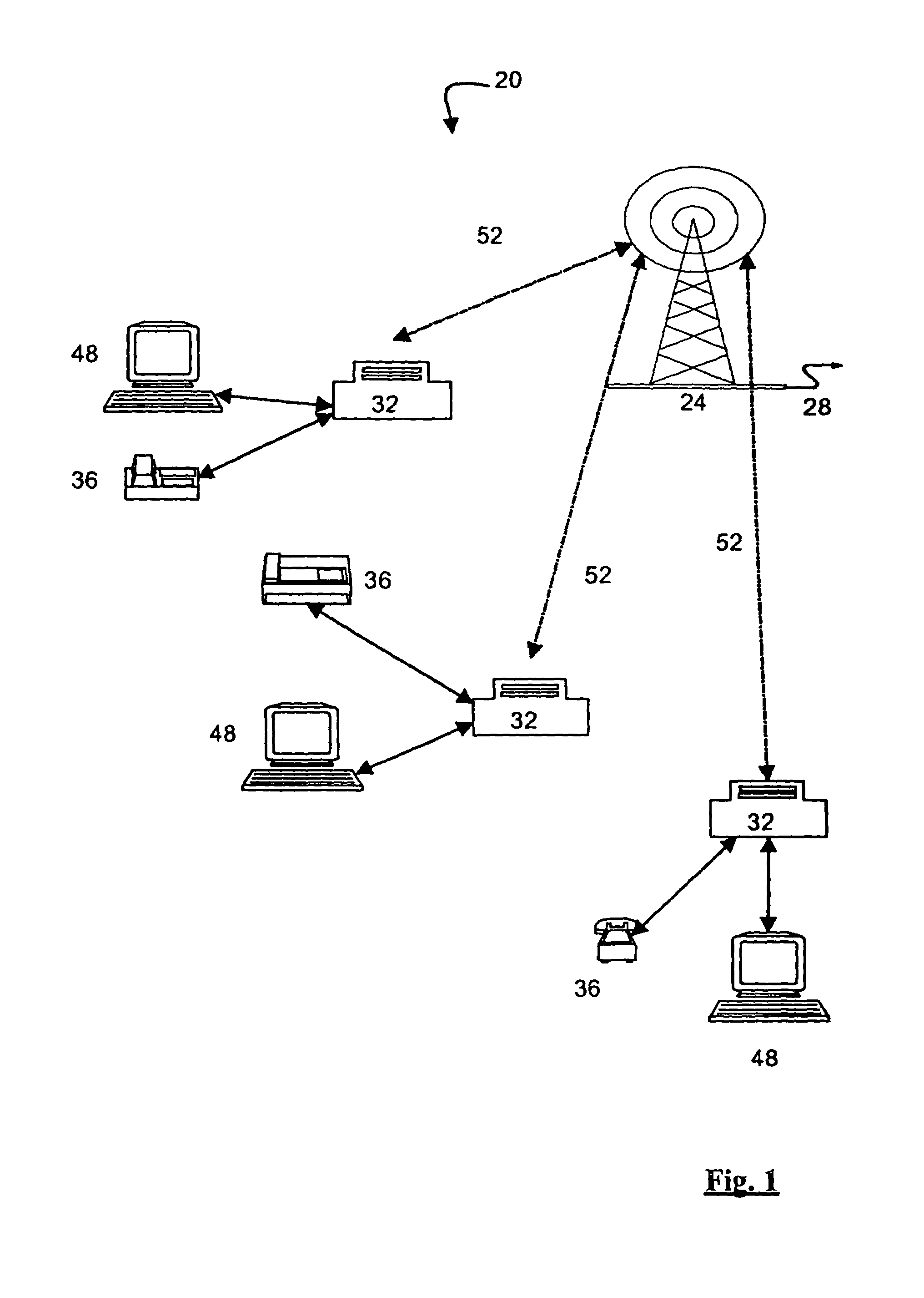
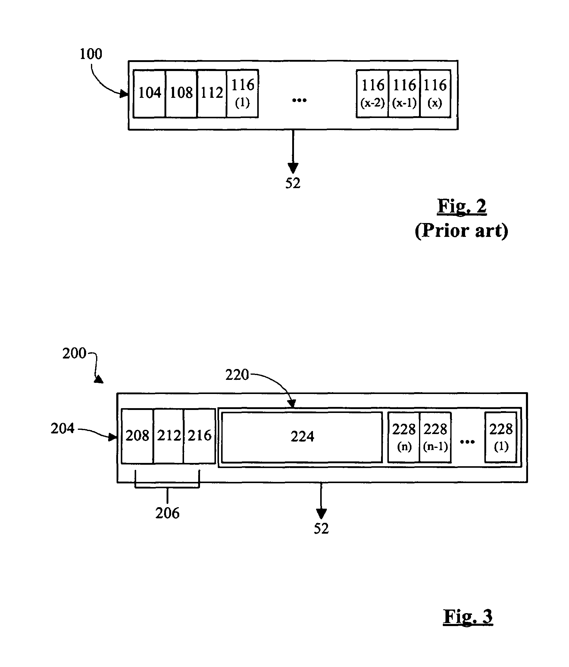
[0033]FIG. 1 shows a wireless local loop (WLL) system, indicated generally at 20. System 20 includes at least one network node, such as base station 24, which is connected to one or more networks, such as the PSTN and / or the Internet, and / or to one or more other base stations 24, via a back haul 28. Backhaul 28 can be any suitable communication link such as a T1, T3, E1, E3, OC3, radio or microwave link. Each base station 24 communicates with a plurality of subscriber stations 32 via a multiplexed radio link 52 shared between subscriber stations 32. In FIG. 1, each subscriber station 32 can provide simultaneous connections to at least one telephony device 36, such as a telephone set or facsimile machine, and a data device 48 such as a computer, video conferencing system, etc.

[0034]Radio link 52 employs a suitable multiplexing technique, such as TDMA, FDMA, OFDM, CDMA, hybrids thereof or other multiplexing techniques to allow simultaneous use of radio link 52 by base station 24 and m...


PUM


Abstract

A communication structure and method which allows connection-like and connectionless communications to be provided on a multiplexed link is provided. The structure and method can make efficient use of available transmission capacity and/or network resources while providing both types of communication and hybrids. Connection-like communications can be provided by a channel having allocated transmission capacity dedicated to the communication while connectionless communication can be provided by a shared channel through which data can be transmitted to subscribers. In an embodiment, the shared channel transmits frames of packets addressed to one or more of the subscribers. The allocation of transmission capacity between the dedicated channels and the shared channel can be fixed, or can be managed to meet network or network operator requirements. The structure and method can also be managed by the network operator to permit prioritization of some communications over others. In another embodiment, two or more shared channels are provided.

Description

FIELD OF THE INVENTION[0001]The present invention relates to a communication structure and method. More specifically, the present invention relates to a communication structure and method for transmitting data, which can include both voice data and non-voice, “pure” data, over a multiplexed link.BACKGROUND OF THE INVENTION[0002]Many communications systems are known. Early communications systems were connection-based, in that a connection was physically established through the system between the communicating nodes. For example, in the early versions of the public switched telephone network (PSTN), users were provided a point-to-point connection to other users through switchboards, switches and trunks. More recently, the PSTN has employed multiplexed lines that are shared, through at least some part of the network, by multiple users, but which still provide a fixed amount of bandwidth and network capacity to each user for their voice data connection, these bandwidth and network capac...

Claims


Application Information

Patent Timeline
IPC IPC(8): H04J3/16
CPCH04J3/1682H04W28/20H04W36/16
Inventor FRAZER, MARK J.VAN HEESWYK, FRANK MKSCHISCHANG, FRANKMANTHA, RAMESHSNELGROVE, W. MARTIN
Owner SAMSUNG ELECTRONICS CO LTD
Why Eureka
Try Eureka