
System for surveillance of spectral signals

a spectral signal and system technology, applied in the field of system for monitoring spectral signals, can solve the problems of conventional problems such as false alarms, delay in alarms, and inability to perceive the onset of process disturbances or sensor deviations by most conventional methods, and achieve the effect of enhancing sensitivity to deviations and removing unwanted serial correlation nois

Inactive Publication Date: 2006-02-14
ARCH DEVMENT
View PDF7 Cites 20 Cited by
  • Summary
  • Abstract
  • Description
  • Claims
  • Application Information

AI Technical Summary

Problems solved by technology

These conventional methods suffer from either large numbers of false alarms (if thresholds are set too close to normal operating levels) or a large number of missed (or delayed) alarms (if the thresholds are set too expansively).
Moreover, most conventional methods cannot perceive the onset of a process disturbance or sensor deviation which gives rise to a signal below the threshold level for an alarm condition.
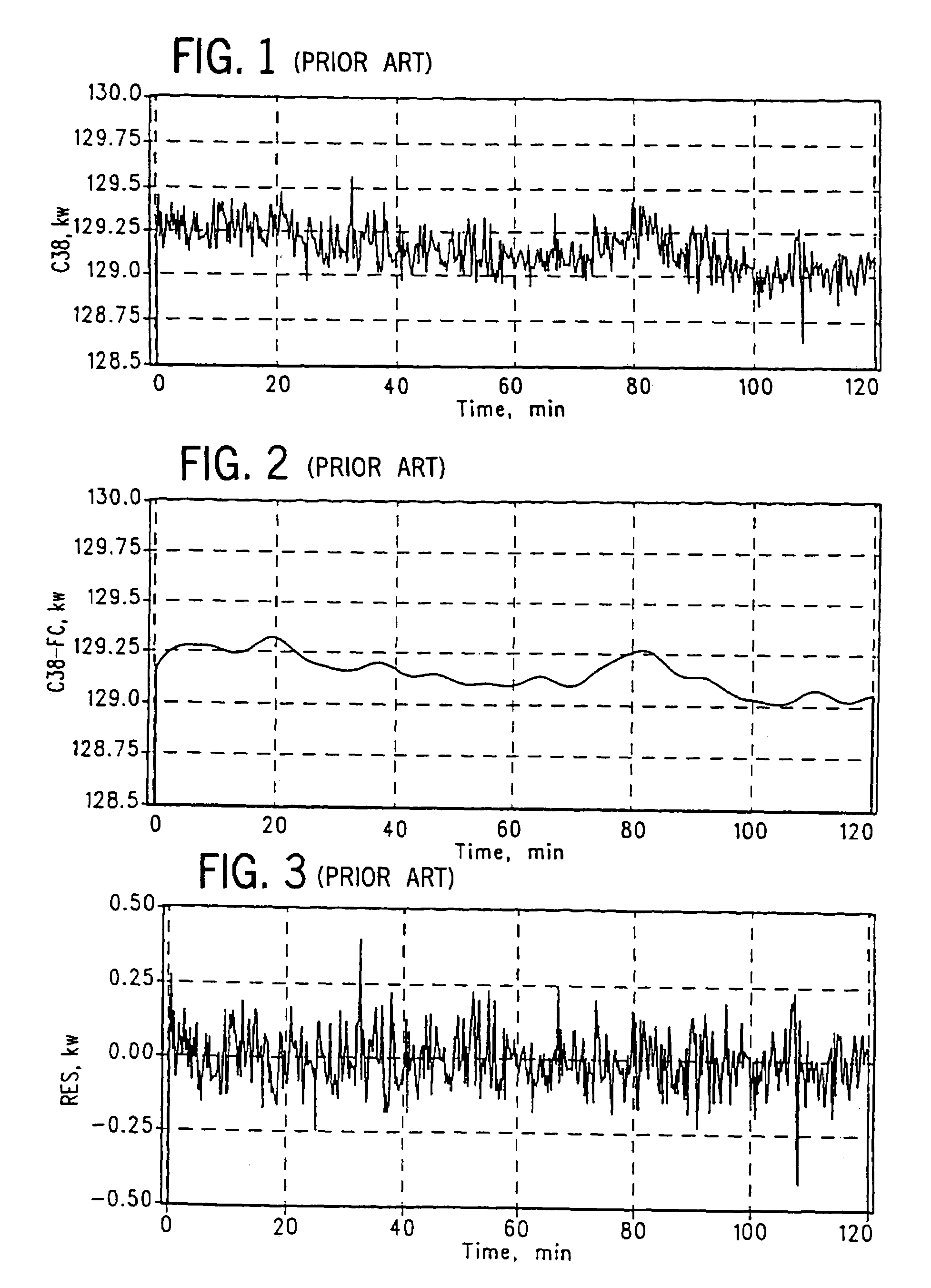
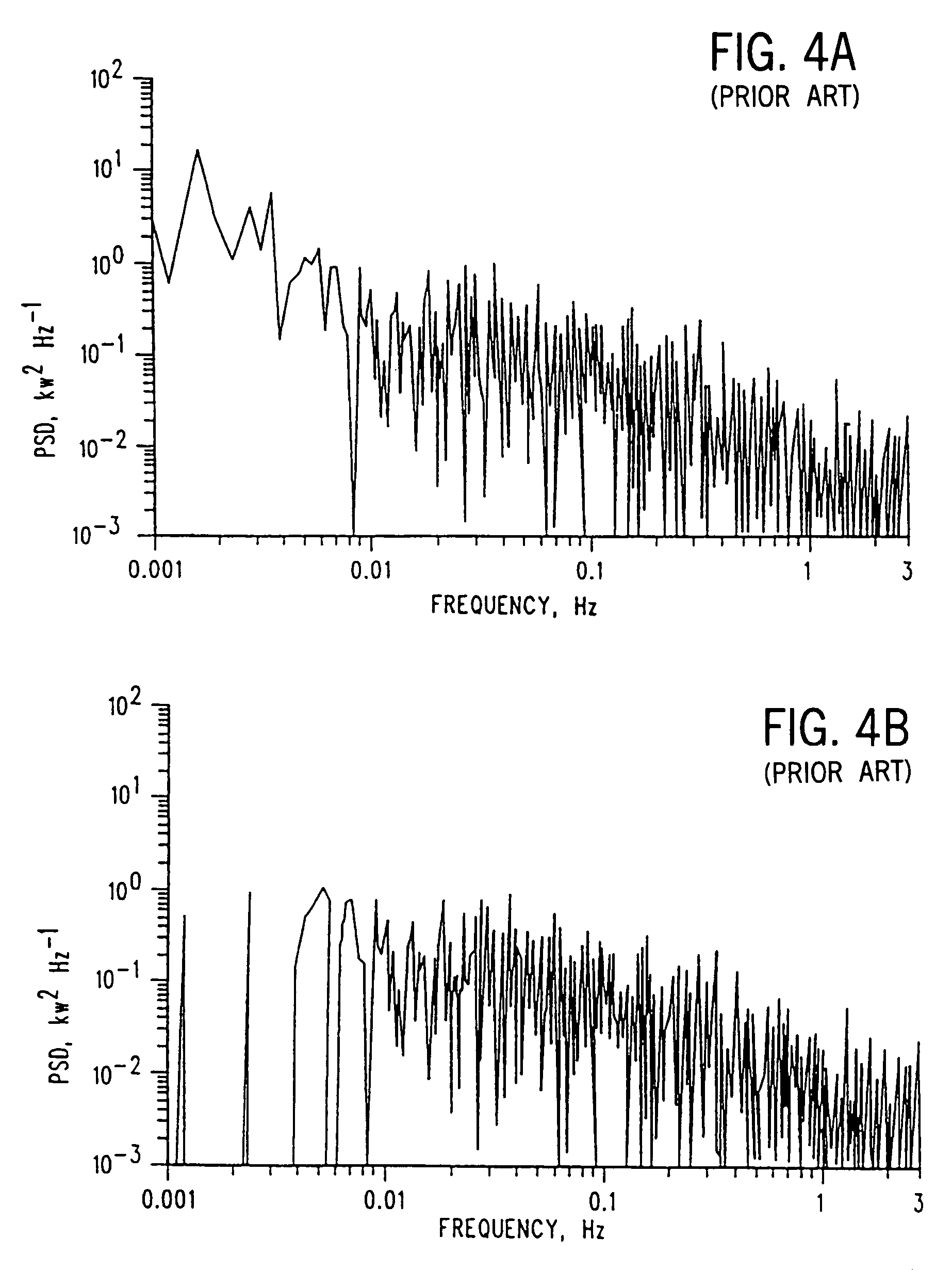
Some drawbacks of these conventional systems that are based on examination of PSDs include: (1) most conventional systems rely on a human to examine the PSD spectra to look for changes in the abscissa or ordinate of peaks of interest; and (2) if one tries to automate the surveillance of PSD information by assigning thresholds for the amplitudes of various peaks of interest, then one encounters the conventional problem of false and missed alarms.
If one tries to avoid this problem by setting the thresholds further apart, then the degradation in the equipment or process can be much worse.
One important drawback of the SPRT technique that has limited its adaptation to a broader range of applications is the fact that its mathematical formalism is founded upon an assumption that the signals it is monitoring are purely Gaussian, independent (white noise) random variables.

Method used


Image

  • System for surveillance of spectral signals
  • System for surveillance of spectral signals
  • System for surveillance of spectral signals

Examples


Embodiment Construction

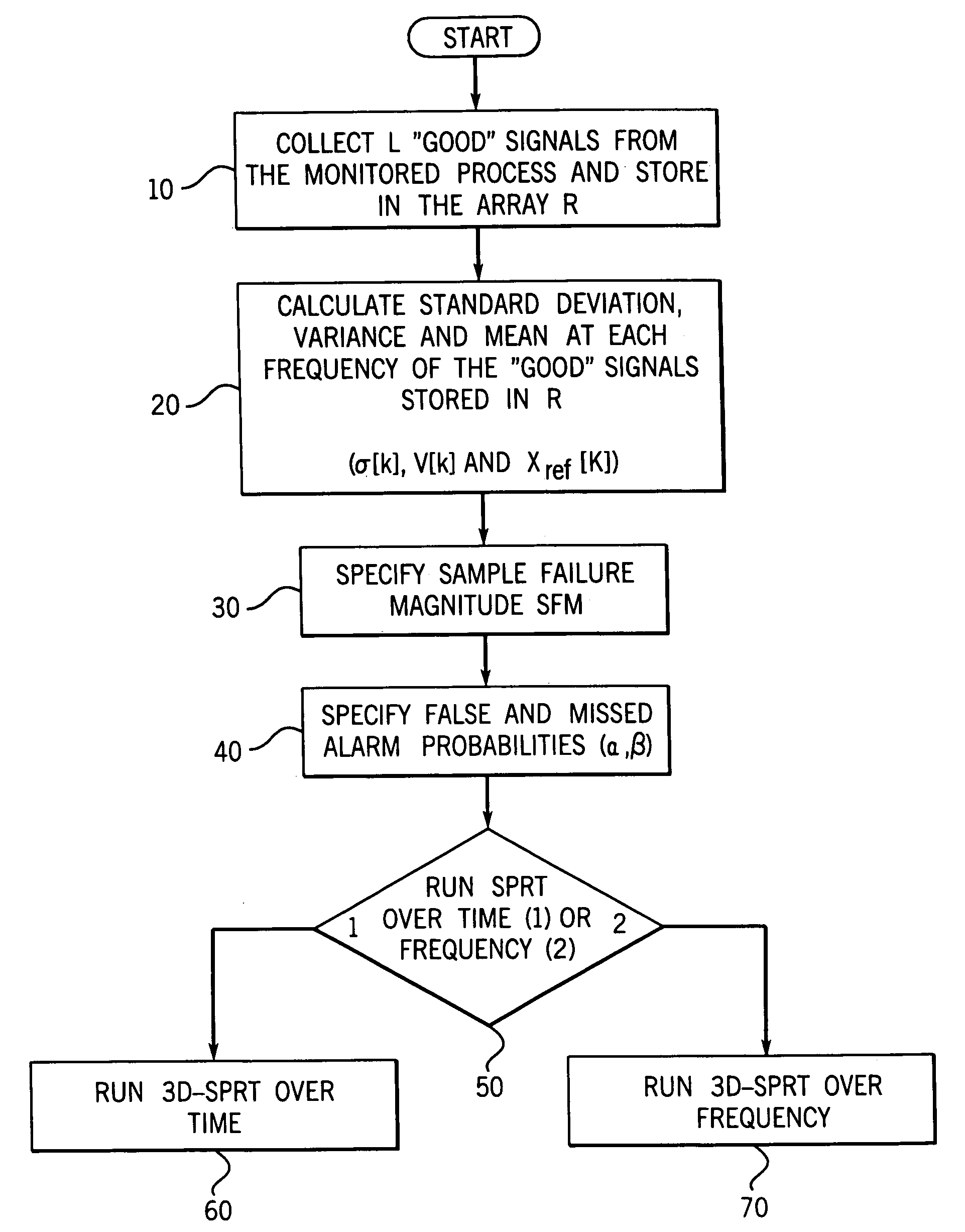
[0046]A system and method of the invention are illustrated in the figures with a detailed flow diagram of preferred embodiments shown in FIGS. 9A and 9B. In a preferred form of the invention, a time domain spectrum of signals is being analyzed, or validating an already existing data stream, which can be processed by a probabilistic methodology and then combined with a frequency domain transformation, such as by Fourier transformation, to generate a three-dimensional surface plot characteristic of the operating state of an underlying system or of a source of signals.

[0047]In a most preferred embodiment, the probabilistic method utilized is the sequential probability ratio test (SPRT) which in this invention can operate either in the time domain or the frequency domain. This methodology is set forth in great detail hereinafter. The SPRT methodology is applied to a power spectral density (PSD) function (or to the real and imaginary parts of the complex Fourier transform) created by per...


PUM

PropertyMeasurementUnit
temperatureaaaaaaaaaa
frequencyaaaaaaaaaa
frequencyaaaaaaaaaa

Abstract

A method and system for monitoring at least one of a system, a process and a data source. A method and system have been developed for carrying out surveillance, testing and modification of an ongoing process or other source of data, such as a spectroscopic examination. A signal from the system under surveillance is collected and compared with a reference signal, a frequency domain transformation carried out for the system signal and reference signal, a frequency domain difference function established. The process is then repeated until a full range of data is accumulated over the time domain and a Sequential Probability Ratio Test (“SPRT”) methodology applied to determine a three-dimensional surface plot characteristic of the operating state of the system under surveillance.

Description

CROSS-REFERENCE TO RELATED PATENT APPLICATIONS[0001]This application is a Continuation of U.S. application Ser. No. 10 / 155,155, filed May 28, 2002, now U.S. Pat. No. 6,804,628 incorporated herein by reference in its entirety, which is a Continuation of U.S. application Ser. No. 09 / 858,786, filed May 16, 2001, now U.S. Pat. No. 6,553,334 and is incorporated herein by reference in its entirety, which is a Continuation of U.S. application Ser. No. 08 / 970,873, filed Nov. 14, 1997, now U.S. Pat. No. 6,240,372 and is incorporated herein by reference in its entirety.[0002]The U.S. Government has rights in this invention pursuant to Contract W-31-109-ENG-38 between the U.S. Department of Energy and the University of Chicago.[0003]The present invention is concerned generally with a system and method for monitoring processes and systems producing any type of spectra as well as ones having signals with periodic components. More particularly, the invention is concerned with a system and method ...

Claims


Application Information

Patent Timeline
Patent Type & Authority Patents(United States)
IPC IPC(8): G06F7/00G01N21/35G01N21/64G01R23/16
CPCG01R23/16
Inventor GROSS, KENNETH C.WEGERICH, STEPHAN W.CRISS-PUSZKIEWICZ, CYNTHIAWILKS, ALAN D.
Owner ARCH DEVMENT
Learn More