Reynolds number correction function for mass flow rate sensor

a mass flow rate sensor and number correction technology, which is applied in the field of mass flow rate sensors, can solve the problems of major source of error in measuring gas flow, major reynolds loss, and change in bypass ratio for different gases, and achieves cost-effective and time-consuming solutions

Active Publication Date: 2006-02-21
MKS INSTR INC
View PDF4 Cites 30 Cited by
  • Summary
  • Abstract
  • Description
  • Claims
  • Application Information

AI Technical Summary

Benefits of technology

[0011]The present disclosure provides a new and improved thermal mass flow rate sensor. The sensor includes a main conduit including an upstream portion connected to an inlet of the sensor and a downstream portion connected to an outlet of the sensor, and a sensor tube and a bypass tube connecting the upstream portion of the main conduit

Problems solved by technology

However, the bypass ratio changes for different gases because of pressure losses (i.e., bypass ratio error), such as entrance effects, caused by non-ideal geometric conditions of the primary conduit, the bypass tube and

Method used


Image

  • Reynolds number correction function for mass flow rate sensor
  • Reynolds number correction function for mass flow rate sensor
  • Reynolds number correction function for mass flow rate sensor

Examples


Embodiment Construction

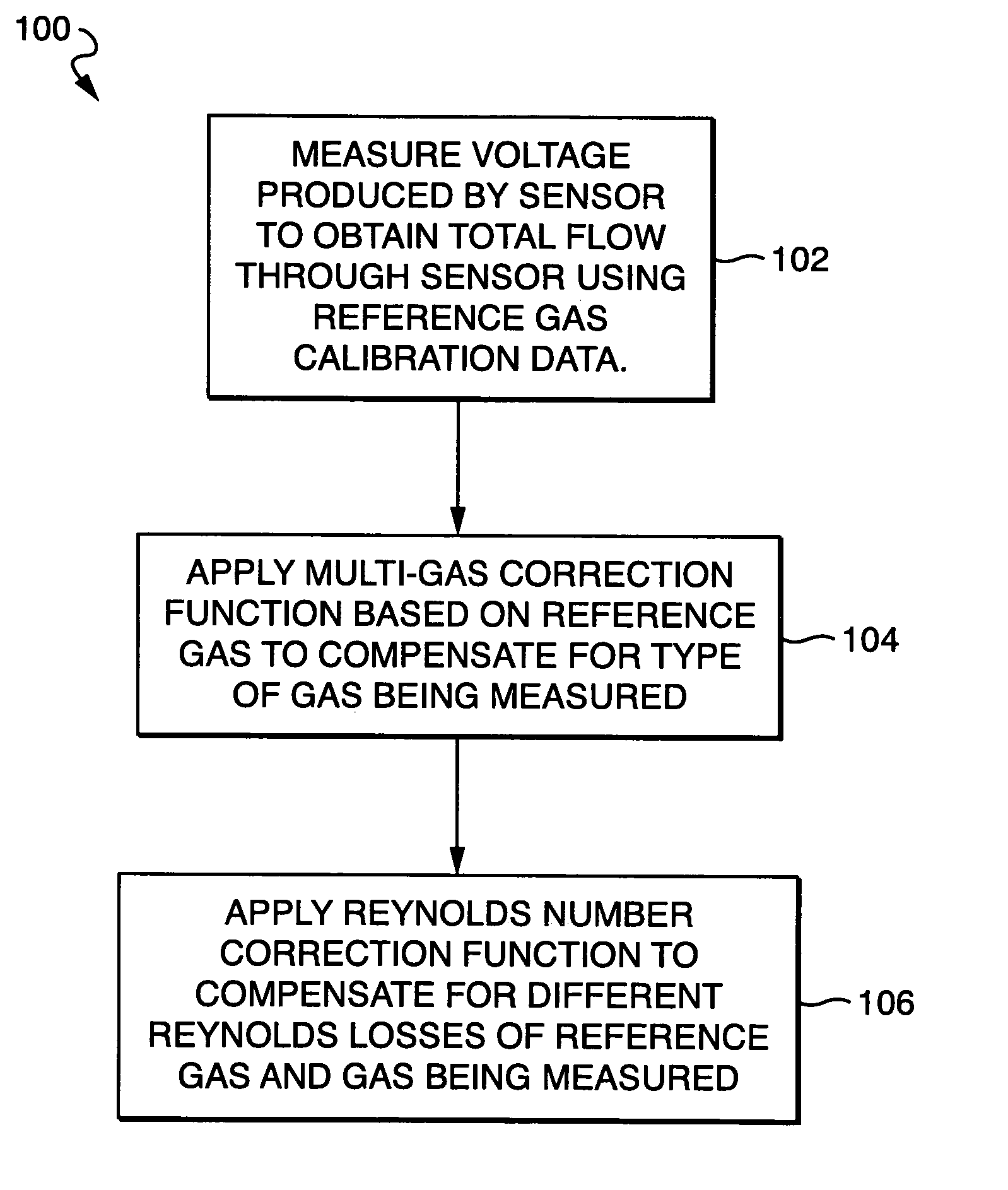
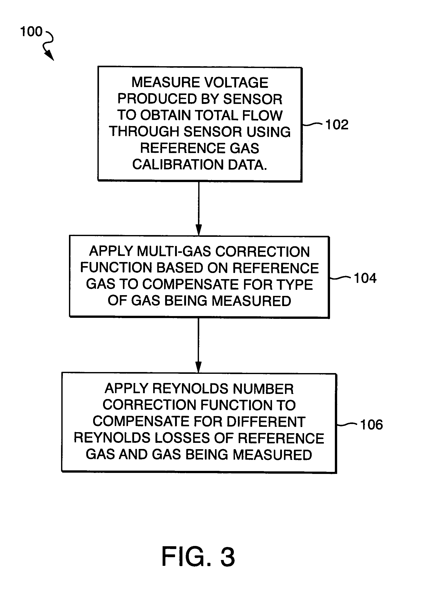
[0023]Referring to the drawings, FIG. 3 shows an exemplary embodiment of a control algorithm 100 provided in accordance with the present disclosure for use by a thermal based mass flow controller (MFC), such as the prior art MFC shown in FIGS. 1 and 2. In such an application, the control algorithm 100 of the present disclosure is programmed into a processor 24 of the MFC. The present disclosure is also directed to a method of measuring flow and a method of controlling flow using the control algorithm 100 of FIG. 3.

[0024]Among other features and benefits, the control algorithm 100 of the present disclosure operates the MFC substantially independently of gas properties. In addition, the control algorithm 100 of the present disclosure provides compensation for the Reynolds Losses of different gases.

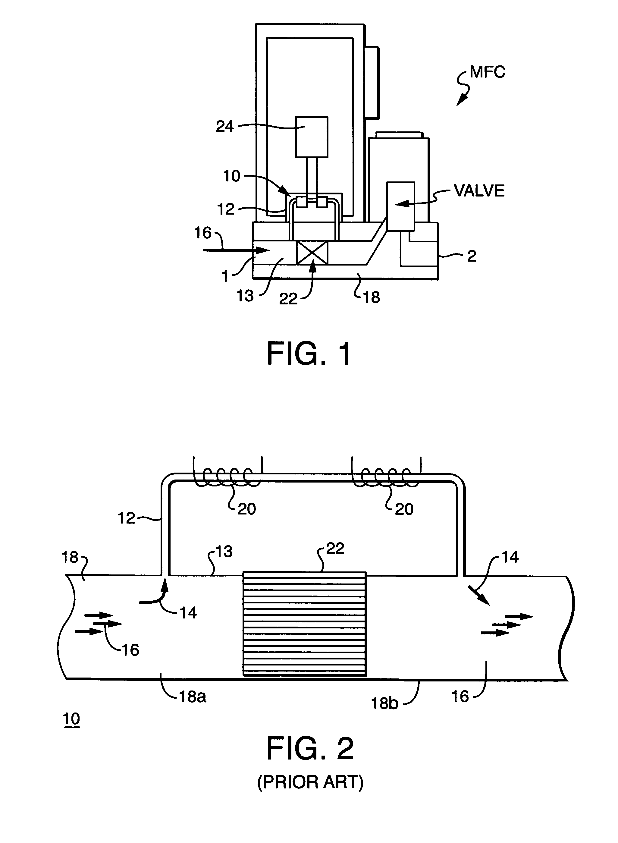
[0025]In FIG. 1 there is shown an example of a typical MFC. The MFC generally includes a main conduit 18 including an upstream portion 18a connected to an inlet 1 of the MFC and a downstream...


PUM


Abstract

A mass flow rate sensor uses a Reynolds number correction function to compensate for errors in a bypass ratio of the sensor for all gases, based on the fact that all bypass errors are functions of Reynolds number. The sensor includes a sensor tube and a bypass tube dividing flow, wherein a bypass ratio of the sensor equals a total flow rate through the sensor divided by a flow rate through just the sensor tube. Heater elements heat an upstream portion and a downstream portion of the sensor tube, and a circuit is connected to the heater elements for producing a voltage based upon a difference in resistance between the heater elements. The voltage is calibrated based on known flow rates of a reference gas, and the flow rate through the sensor is based upon the calibrated voltage multiplied by a multi-gas correction function and a Reynolds number correction function.

Description

FIELD OF THE INVENTION[0001]The present disclosure relates to mass flow rate sensors, and more particularly, to a thermal based mass flow rate sensor incorporating a bypass ratio Reynolds number correction function.BACKGROUND OF THE DISCLOSURE[0002]In the semiconductor manufacturing industry, it is necessary to achieve precise control of the quantity, temperature and pressure of one or more reactant materials which are delivered in a gaseous state to a reaction chamber. Mass flow controllers (MFC) are widely used in the semiconductor manufacturing industry to control the delivery of process reactants.[0003]A typical MFC generally includes a main conduit including an upstream portion connected to an inlet of the MFC and a downstream portion connected to an outlet of the MFC. The MFC also includes a mass flow rate sensor for measuring the rate of flow of gas through the MFC, a valve for controlling the flow of gas through the MFC and a simple control circuit or a computer mounted on a...

Claims


Application Information

Patent Timeline
IPC IPC(8): G01F1/68
CPCG01F1/6847G01F15/046G01F5/00G01F1/6965G01F15/043G01F1/684G01F1/696G01F15/04
Inventor SHAJII, ALIMENEGHINI, PAUL
Owner MKS INSTR INC
Why Eureka
Try Eureka