Motor pack for automated machinery

a technology of motor packs and automatic machinery, which is applied in the field of motor pack motors for motors, can solve the problems of retarding the adoption of electrically powered tools, the complexity of conventional control systems for electrically powered tools,

Inactive Publication Date: 2006-02-21
DELAWARE CAPITAL FORMATION INC +1
View PDF4 Cites 824 Cited by
  • Summary
  • Abstract
  • Description
  • Claims
  • Application Information

AI Technical Summary

Problems solved by technology

However, the complexity of conventional control systems for electrically powered tools is a significant disadvantage that has retarded the adoption of electrically powered tools in the automation industry.

Method used


Image

  • Motor pack for automated machinery
  • Motor pack for automated machinery
  • Motor pack for automated machinery

Examples


third embodiment

[0059]Referring now to FIGS. 10 and 11, the present invention is depicted as an electric clamp 310. Electric clamp 310 has a housing 312 and a number of other components including a lead screw 324, which are all entirely enclosed within housing 312. Clamp 310 is similar to the preceding embodiments in many respects, but differs primarily in the manner in which it manipulates the output shaft 330 and clamp arm 331. In particular, clamp 310 uses a single electric motor 314, which is preferably a linear actuator, to advance and retreat a lead screw 324 extending axially through the motor 314. Consequently, no separate ball nut hub or ball nut is required.

[0060]The lead screw 324 is further coupled to the output shaft 330 through components such as a linkage 326 and a piston 333. The piston 333 is mounted in a chamber 335 that is located within the housing 312. In this disclosure, the terms piston and chamber are not necessarily used in the conventional sense to include a sealing relati...

fourth embodiment

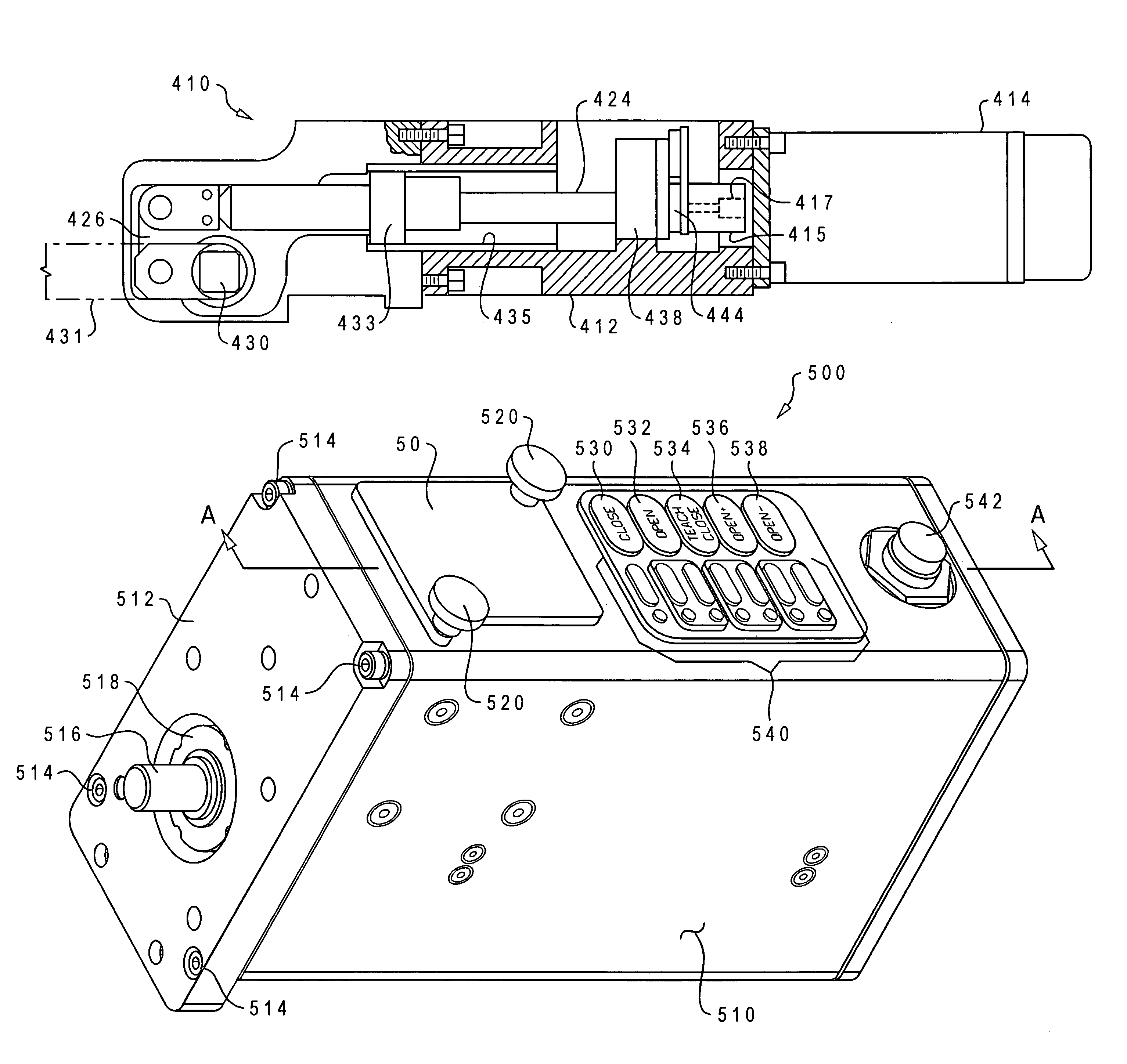
[0061]Referring now to FIGS. 12 and 13, the present invention is depicted as an electric clamp 410. Clamp 410 utilizes many of the components and features of the preceding embodiments, including a housing 412 and an electric motor 414 with a drive shaft 417 that is rotatable about an axis. In the depicted embodiment, motor 414 is mounted to an exterior of the housing 412, and drive shaft 417 protrudes into the housing 412. A helical coupling 415 is mounted to drive shaft 417 and is coupled to a ball nut hub (not shown). A ball screw 424 extends axially through the ball nut hub such that the ball screw 424 is axially advanced and retreated by rotation of the ball nut hub. The ball screw 424 is entirely enclosed within the housing 412. The housing 412 also contains a chamber 435 that is coaxial with the drive shaft 417. A piston 433 is located in the chamber 435, and the piston 433 is coupled to the ball screw 424 such that movement of the ball screw 424 by the electric motor 414 move...


PUM


Abstract

A motor pack for an electrically driven tool includes at least one electric motor and a linearly displaceable member coupled to the electric motor such that the linearly displaceable member is displaced axially by operation of the at least one electric motor. The motor pack further includes a housing enclosing the electric motor and at least partially enclosing the linearly displaceable member. The housing includes a front plate to which a tool head may be removably coupled. The front plate has an aperture formed therein through which the linearly displaceable element can be coupled to a moveable element in the tool head. The motor pack also includes tool control circuitry enclosed within the housing and electrically coupled to the electric motor to control operation thereof.

Description

[0001]The present application is a continuation-in-part of U.S. patent application Ser. No. 10 / 640,200, filed Aug. 13, 2003, which is a continuation of U.S. patent application Ser. No. 10 / 321,880 filed on Dec. 17, 2002, now U.S. Pat. No. 6,644,638, which is a continuation-in-part of U.S. patent application Ser. No. 09 / 887,293 filed on Jun. 22, 2001, now U.S. Pat. No. 6,585,246. All of the foregoing applications are incorporated herein by reference in their entireties.BACKGROUND OF THE INVENTION[0002]1. Technical Field[0003]This invention is related to motor-driven machinery and tools, and in particular, to a motor pack for motor-driven tools.[0004]2. Description of the Related Art[0005]The robotics and automation industry employs a number of tools, such as clamps, pin clamps, hook pin clamps and grippers, to secure, manipulate and / or transport objects, for example, components of an assembly. Although electrically powered tools are generally more quiet than pneumatically powered tool...

Claims


Application Information

Patent Timeline
Patent Type & Authority Patents(United States)
IPC IPC(8): B25B1/04B25B5/12B25B5/16
CPCB25B5/12B25B5/16B25B5/122
Inventor MCCORMICK, PETER E.BEALL, DANIEL ALAN
Owner DELAWARE CAPITAL FORMATION INC
Why Eureka
Try Eureka