Water vehicle propeller

a propeller and water vehicle technology, applied in watercraft, marine propulsion, vessel construction, etc., can solve the problems of not being the application of the theory to the operation of the marine screw propeller is extremely complicated and not definitively known, and the water vehicle having a conventional prior art propeller system is not able to generate the propulsion force needed to accomplish, etc., to achieve the effect of increasing the maneuverability of watercra

Inactive Publication Date: 2006-02-21
KETTELSON ERNEST
View PDF7 Cites 3 Cited by
  • Summary
  • Abstract
  • Description
  • Claims
  • Application Information

AI Technical Summary

Problems solved by technology

The confused nature of the water at the stern of a moving boat makes the application of theory to marine screw propeller operation extremely complicated and not definitively known.
In any event, there is considerable slippage with the conventional screw propellers as between the distance advanced in the water compared to the linear feet of water actually passed through the propeller blades.
No manufactured water vehicle having a conventional prior art propeller system is able to generate the propulsion force needed to accomplish that.
Another disadvantage of conventional screw propeller water craft is that large portions of the hull are in sliding-frictional contact with the water, requiring the propellers to push the hull head-on against the resistance of the water displaced with no means throughout such hull surface to assist in moving the craft forward.
Conventional screw propeller water craft also encounter what is known as wave resistance, separate and apart from frictional resistance, thus incurring additional energy loss due to wave making.

Method used


Image

  • Water vehicle propeller
  • Water vehicle propeller
  • Water vehicle propeller

Examples


Embodiment Construction

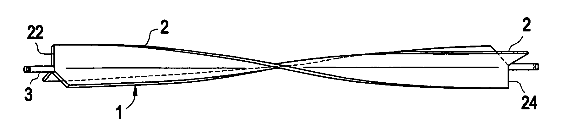
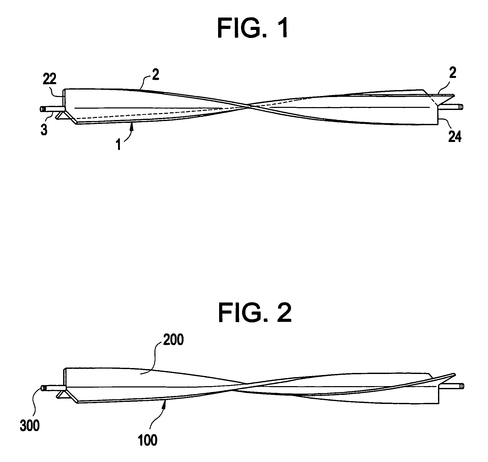
[0025]Referring now to the drawings in detail, FIG. 1 shows a propeller 1 made in accordance with this invention, having helical blades 2 which extend in a partially helical path in a right-hand-turn helical direction, affixed to an elongated shaft 3, such as by welding or the like.

[0026]FIG. 2 shows a propeller 100 also made in accordance with this invention, having helical blades 200 which extend in a partially helical path in a left-hand turn helical direction, affixed to an elongated shaft 300, such as welding or the like.

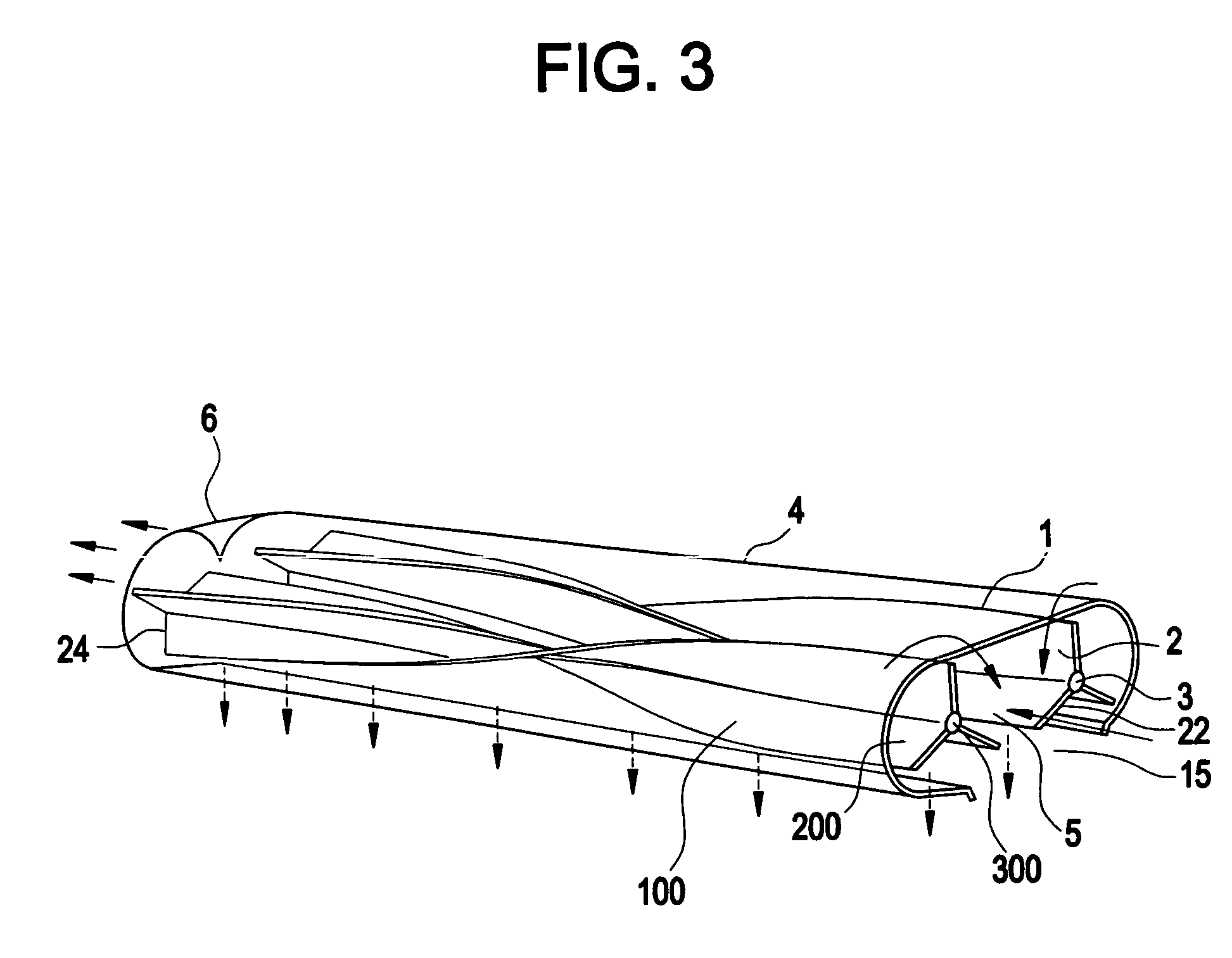
[0027]The longitudinal axes of propellers 1 and 100 have a length that is preferably about the same as the length of that portion of the boat that is normally in the water when under way. The longitudinal axes of propellers 1 and 100 in accordance with this invention have a length or longitudinal dimension that is greater than the radius of rotation, i.e. greater than the width of the helical blades 2 and 200. In other words, the helical blades 2 and 200 and el...


PUM


Abstract

In this specification regarding water vehicle propellers, the gist of the technical disclosure resides in the construction of a propeller having elongated blades which extend in a helical path and longitudinally of the hull of a water vehicle in an unbroken length, singly or in aligned sections following the contour of the hull, for substantially its entire length or that portion of the length of a water vehicle in contact with the body of water when under way. The elongated propellers are rotated on their longitudinal axis. In addition, two of such elongated propellers or aligned sections of such propellers are mounted parallel for rotation in opposite directions either within a tubular housing open at the front and rear or mounted directly adjacent the hull with one or more on either side. Spaced apart longitudinal support members are secured below the elongated propellers to prevent contact with an object or objects from below and to support the propellers and hull above any such objects. One of such propellers may be mounted below a forward portion of a vessel and a second below a rearward portion, each propeller being pivotable outwardly in opposite directions from the longitudinal axis of the vessel to enable the vessel to turn more rapidly from one direction to another.

Description

FIELD OF THE INVENTION[0001]This invention relates to a new and useful propeller and propulsion system for water vehicles.BACKGROUND OF THE INVENTION[0002]The most common means now employed to move power boats through the water is the longitudinally short screw propeller. The theory of the action of the screw propeller has been the subject of consideration by many investigators. One theory is that the propeller impresses change of motion upon the water without change of pressure except such as is caused by the rotation of the screw. Another theory is that the thrust is obtained by change of pressure, the only changes of motion being the circumferential velocity due to the rotation of the propeller. Still others are referred to as the momentum theory and the vortex theory. The confused nature of the water at the stern of a moving boat makes the application of theory to marine screw propeller operation extremely complicated and not definitively known. In any event, there is considerab...

Claims


Application Information

Patent Timeline
Patent Type & Authority Patents(United States)
IPC IPC(8): B63H1/26B63H1/12B63H5/16
CPCB63H1/12B63H5/16B63H2023/005B63H2001/122
Inventor KETTELSON, ERNEST
Owner KETTELSON ERNEST
Why Eureka
Try Eureka