Ultrasonic wave generating/transmitting apparatus

a technology which is applied in the field can solve the problems of inconvenient enlargement of ultrasonic generating and transmitting apparatus

Inactive Publication Date: 2006-02-21
HITACHI LTD
View PDF13 Cites 278 Cited by
  • Summary
  • Abstract
  • Description
  • Claims
  • Application Information

AI Technical Summary

Benefits of technology

[0006]The present invention is directed to an ultrasonic generating and transmitting apparatus equipped with a transmission section for transmitting ultrasonic vibration from a vibration section. According to a preferable embodiment of the present invention, there are provided a plurality of linear members for transmitting ultrasonic vibration, and binding means for binding the linear members in such a state as to be apart from one another, and the transmission section is comprised of those linear members and binding means. As the plural linear members bound are separated from one another, heat generation between adjoining linear members which are transmitting ultrasonic vibration is avoided.
[0007]According to another embodiment of the present invention, an ultrasonic generating and transmitting apparatus is equipped with a vibration section for generating ultrasonic, an insert tube coupled to the vibration section and an operational section which is located at a distal end of the insert tube and to which ultrasonic vibration is transmitted. The insert tube has a plurality of linear members, a plurality of binding plates for binding the plurality of linear members and a protection cover for covering around the plurality of linear members and the plurality of binding plates. Even such an embodiment affords operational advantages similar to those of the aforementioned embodiment. Further, the protection cover prevents the vibration portions of the other linear members than the distal end portions from contacting something other than the ultrasonic generating and transmitting apparatus.

Problems solved by technology

The enlargement of an ultrasonic generating and transmitting apparatus is particularly inconvenient in an ultrasonic treatment device or the like which is used by inserting it in a human body.

Method used


Image

  • Ultrasonic wave generating/transmitting apparatus
  • Ultrasonic wave generating/transmitting apparatus
  • Ultrasonic wave generating/transmitting apparatus

Examples


first embodiment

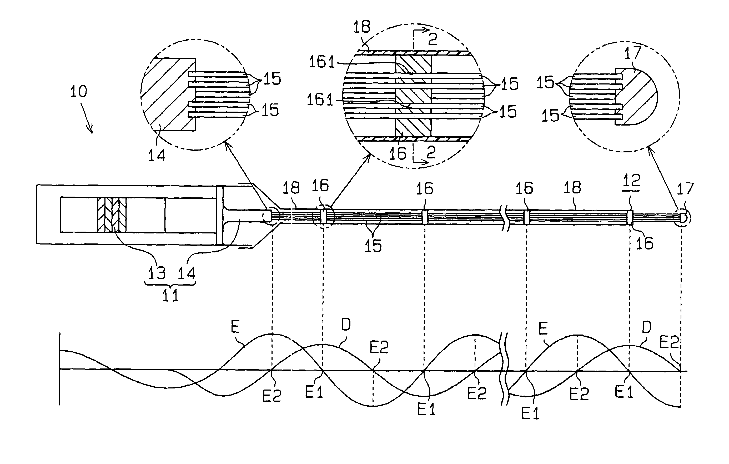
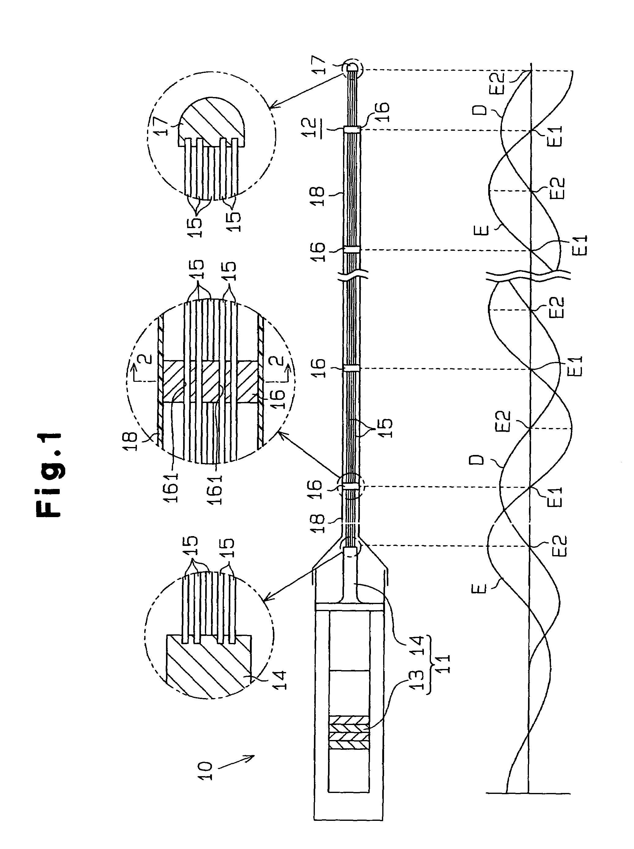
[0013]an ultrasonic generating and transmitting apparatus embodying the present invention will be described below based on FIGS. 1 to 3. FIG. 1 shows an ultrasonic generating and transmitting apparatus 10 with a structure suitable for an ultrasonic treatment device. The ultrasonic generating and transmitting apparatus 10 comprises a vibration section 11 which generates ultrasonic and an insert tube 12 coupled to the vibration section 11.

[0014]The vibration section 11 has a vibrator 13 which oscillates with the supply of an electric signal, and a conical horn 14 linked to the vibrator 13. A Langevin vibrator, for example, is used in the vibration section 11. The horn 14 amplifies ultrasonic vibration produced by the vibrator 13.

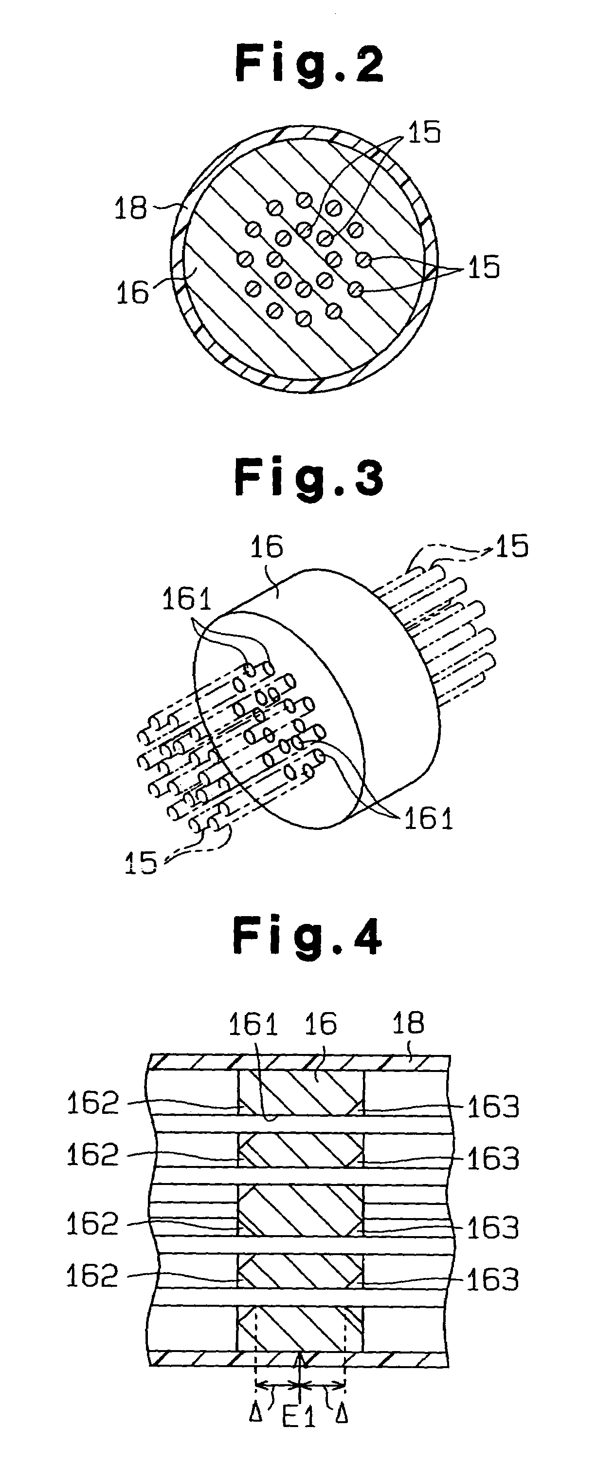
[0015]The insert tube 12 comprises a plurality of linear members 15 with a single core shape, a plurality of disk-like binding plates 16 which bind the plural linear members 15, an operational section 17 coupled to the distal end portions of the plural linear ...

second embodiment

[0039](4) The tapers 162 and 163 in the second embodiment may cross each other so that the binding plate 16 has a line contact with the linear members 15.

[0040](5) The binding plates 16, 16A are formed of the same material as that of the linear members 15.


PUM


Abstract

Disclosed is an ultrasonic generating and transmitting apparatus equipped with a transmission section for transmitting ultrasonic vibration from a vibration section. A plurality of linear members for transmitting ultrasonic vibration and binding plates which bind the linear members in such a state as to be apart from one another are provided. The transmission section is comprised of the linear members and the binding plates.

Description

CROSS REFERENCE TO RELATED APPLICATIONS[0001]This application is a national phase of International Application No. PCT / JP01 / 11114 filed Dec. 19, 2001, the disclosures of which are incorporated herein by reference, and which claimed priority to Japanese Patent Application No. 2000-388742 filed Dec. 21, 2000, the disclosures of which are incorporated herein by reference.BACKGROUND OF THE INVENTION[0002]The present invention relates to an ultrasonic generating and transmitting apparatus suitable for use in destruction of calculi, such as a biliary calculus and renal calculus, destruction of cells such as of cancer or the like and ultrasonic cleaning or the like.[0003]An ultrasonic generating and transmitting apparatus of this type is disclosed in Japanese Unexamined Utility Model Publication No. 62-152704 and Japanese Examined Utility Model Publication No. 5-46430. Ultrasonic vibration produced by an ultrasonic vibration section is transmitted via a transmission section which has a plu...

Claims


Application Information

Patent Timeline
Patent Type & Authority Patents(United States)
IPC IPC(8): A61B8/00A61B17/22A61B18/00B06B1/06B06B3/00B06B3/04
CPCB06B3/00
Inventor ADACHI, KAZUNARISUGIMOTO, TSUNEYOSHI
Owner HITACHI LTD
Why Eureka
Try Eureka