Antenna

a technology of helix and antenna, applied in the direction of helical antenna, non-resonant long antenna, resonant antenna, etc., can solve the problem of rather expensive cable type, and achieve the effect of good balan

Inactive Publication Date: 2006-02-21
ETOP TECH
View PDF12 Cites 52 Cited by
  • Summary
  • Abstract
  • Description
  • Claims
  • Application Information

AI Technical Summary

Benefits of technology

[0009]The invention provides an antenna structure with a balun transformer, which is formed on a circuit board. As a result, the helix wire part and the balun transformer are electrically coupled together. The balun tra

Problems solved by technology

This kind of cable

Method used


Image

  • Antenna
  • Antenna
  • Antenna

Examples


Embodiment Construction

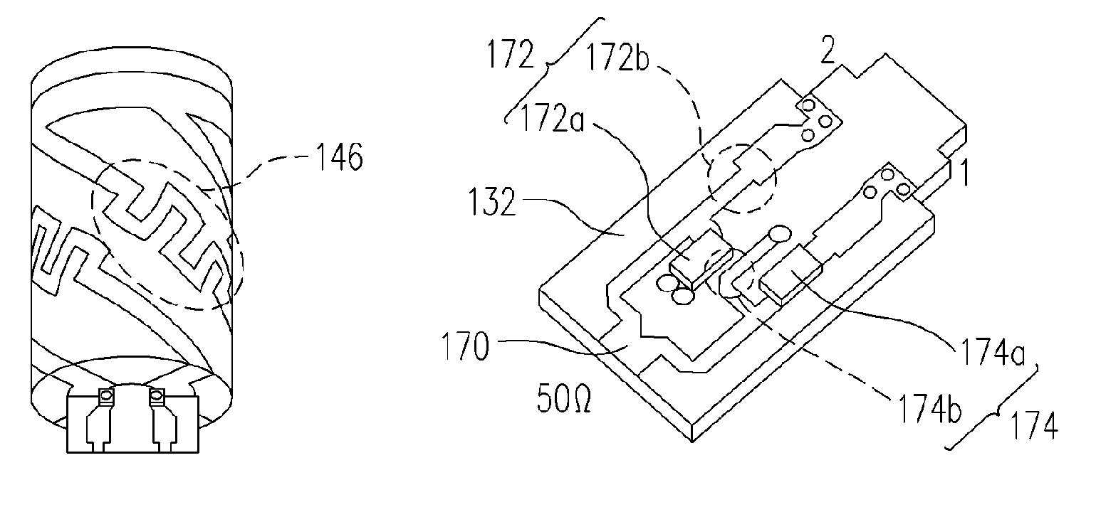
[0027]In the invention, the design principle for the antenna is arranging the balun transformer on a separated circuit board. The antenna radiating part is separated formed on a dielectric core, such as a ceramic rod core. Then, the balun transformer is electrically coupled to the antenna radiating part. Signals are fed from the other end of the balun transformer. The balun transformer has the balun effect and the effect of impedance transformation.

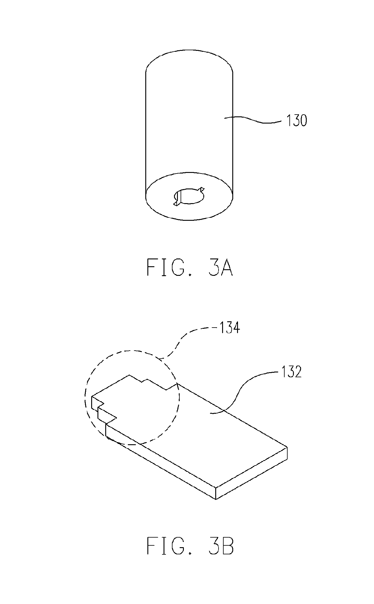
[0028]Embodiments are provided as the examples for descriptions. FIGS. 3A and 3B are perspective drawing, schematically illustrating the parts of the helix antenna, according to an embodiment of the present invention. In FIG. 3A, an antenna core 130 is used as medium material of the antenna. The antenna core 130 can be, for example, a dielectric rod, such as a ceramic rod. A through hole is, for example, formed at the central region. However, this through hole is a design choice, for allowing a circuit board 132 to be easily coupled to th...


PUM


Abstract

An antenna has a central core with a central coupling region. A pair of helix antenna lines is formed a surface of the central core. A balun transformer is formed on a circuit board and electrically coupled to the pair of radiating antenna lines. Wherein, the circuit board has a protruding structure to affixing into the central coupling region of the central core. A signal input/output (I/O) end of the antenna is at another end of the balun transformer. The balun transformer preferably uses the LC resonators in two paths with a desired equivalent resonant length, so as to preferably produce the difference by half wavelength.

Description

BACKGROUND OF THE INVENTION[0001]1. Field of Invention[0002]The present invention relates to an antenna structure. More particularly, the present invention relates to a helix antenna on a dielectric core.[0003]2. Description of Related Art[0004]Antenna is a necessary element in wireless communication. Usually, the radio-frequency (RF) signals, carrying information, are transmitted or received at the antenna. Then, the RF signals are further processed to obtain the actual information be carried. Due to the design of the signal processing circuit, the RF signal in EM-wave has its desired polarization state. Usually, it is a linear polarization or a circular polarization. The polarization state can be generated by a specific antenna structure.[0005]In the modern life, mobile phone has been a very popular wireless communication apparatus. The mobile phone also needs to use the GPS to identify the position. In order to reduce the volume of the GPS unit, the size of antenna is necessary t...

Claims


Application Information

Patent Timeline
IPC IPC(8): H01Q1/36
CPCH01Q1/244H01Q23/00H01Q11/08H01Q1/362
Inventor CHUNG, SHYH-JONGWANG, YU-SHIN
Owner ETOP TECH
Why Eureka
Try Eureka