Thermal pole-tip recession/slide shape variation reduction

a technology of slider and pole tip, which is applied in the direction of maintaining head carrier alignment, mounting head within the housing, instruments, etc., can solve the problems of slider warping over time, over saturated read element,

Inactive Publication Date: 2006-02-21
SEAGATE TECH LLC
View PDF13 Cites 5 Cited by
  • Summary
  • Abstract
  • Description
  • Claims
  • Application Information

AI Technical Summary

Problems solved by technology

On the other hand, if the read element is too close to the disc, the read element may become overly saturated.
One factor

Method used


Image

  • Thermal pole-tip recession/slide shape variation reduction
  • Thermal pole-tip recession/slide shape variation reduction
  • Thermal pole-tip recession/slide shape variation reduction

Examples


Embodiment Construction

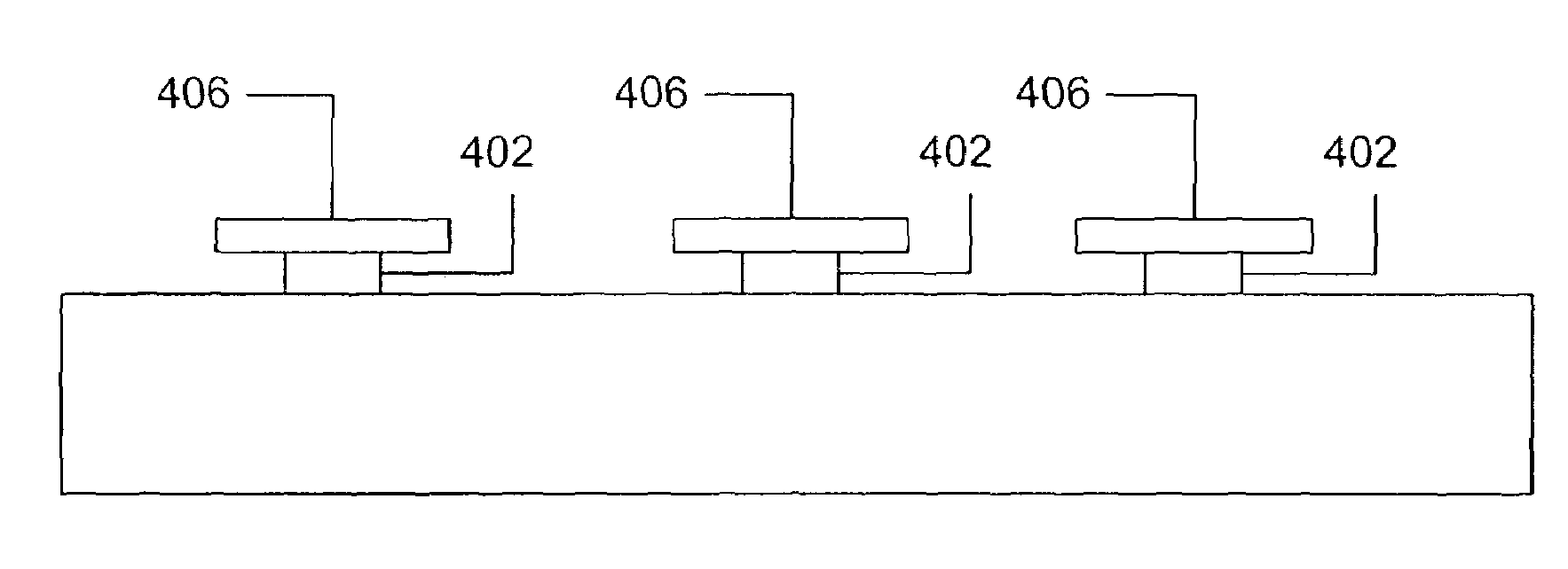
[0019]Slider warpage is caused, in large part, by strain imparted upon the slider body from bond pads attached thereto. As electrical current is passed through a bond pad, the bond pad grows warm, and therefore expands. The expansion of the bond pad results in strain upon the slider body, because the bond pad is attached to the slider body. Armed with this insight into slider warpage, it is evident that reducing the surface area between a bond pad and the slider to which it is attached results in less strain upon the slider and a concomitant reduction in warpage.

[0020]Surface area between a bond pad and a slider can be reduced by the following scheme. The bond pad can be elevated from the slider body by a conductive post. Per such a scheme, the bond pad is perched atop the post, which typically possesses a cross-sectional area smaller than the surface are of the bond pad (the periphery of the bond pad overhangs the supporting conductive post). Thus, rather than having the entire sur...


PUM


Abstract

A bond pad is elevated from a slider body by a conductive post. The bond pad is disposed atop the post, which typically possesses a cross-sectional area smaller than the surface are of the bond pad. Thus, rather than having the entire surface of the bond pad in contact with the slider body, only the cross-sectional area of the conductive post is in contact therewith. Alternatively, a bond pad may be split into two electrically coupled pads: one pad used for housing a permanent bond, and a second pad used for housing a temporary bond. The pad used to house the temporary wire bond may be disposed atop a sacrificial layer. After a lapping process, the sacrificial layer may be etched away, thereby permitting the temporary pad to be removed.

Description

RELATED APPLICATIONS[0001]This application claims priority of U.S. provisional application Ser. No. 60 / 377,139, filed May 2, 2002 and entitled “THERMAL PTR / SLIDER SHAPE VARIATION REDUCTION METHOD.”FIELD OF THE INVENTION[0002]This application relates generally to an apparatus and method for reduction of thermally induced shape distortion of an electronic device, and more particularly to reduction of pole-tip recession in a slider used in a storage device.BACKGROUND OF THE INVENTION[0003]The storage medium for a disc drive is a flat, circular disc capable of retaining localized magnetic fields. The data that are stored upon the disc find physical representation through these localized magnetic fields. The data are arranged on the disc in concentric, circular paths known as tracks.[0004]The localized magnetic fields can be detected by a magnetically sensitive element (“a read element”) when they are brought in close proximity to the element. During operation the disc continually rotate...

Claims


Application Information

Patent Timeline
IPC IPC(8): G11B21/20G11B5/10G11B5/105G11B5/31G11B5/48G11B5/60
CPCG11B5/6005G11B5/4853G11B5/3106G11B5/102G11B5/105G11B5/488
Inventor ZHU, JIANXINSTOVER, LANCE EUGENEJONES, GORDON MERLE
Owner SEAGATE TECH LLC
Why Eureka
Try Eureka