Lens control system and focus information display apparatus

a control system and display device technology, applied in the field of lenses control systems, can solve the problems of insufficient accuracy of marking with tapes or the like, difficulty in accurately aligning the manual operation member to the marked position, and high time and labor requirements of the above method for marking operations, etc., to achieve the effect of reproducing easily and accurately

Active Publication Date: 2006-02-21
FUJI PHOTO OPTICAL CO LTD
View PDF5 Cites 15 Cited by
  • Summary
  • Abstract
  • Description
  • Claims
  • Application Information

AI Technical Summary

Benefits of technology

[0008]The present invention is provided in view of these circumstances. It is an object of the present invention to provide a lens control system that enables an accurate focus position already obtained using an auto focus function to be easily reproduced using a manual focus function.
[0009]It is another object of the present invention to provide a focus information display device that enables a pre-stored focus position to be easily and accurately reproduced.
[0012]According to the present invention, the focus position obtained using the auto focus function is recorded in accordance with the instruction from the predetermined instructing device. Then, this position is displayed on the predetermined display device during focusing using the manual focus function. Consequently, the focus position obtained using the auto focus function can be easily reproduced during the focusing using the manual focus function. Therefore, if the present invention is used for a lens control system for film making, it is possible to accurately focus on a predetermined subject during test photographing using the auto focus function and then to easily reproduce, during actual photographing, the focus position obtained during the test photographing by manual focusing. The present invention is thus suitable for such a lens control system.
[0016]According to the present invention, the display state of the predetermined character, symbol, or graphic is changed to provide the information indicating how the pre-stored focus present position (focus stored position) and the present focus position (focus present position) are close to each other. The pre-stored focus position can be reproduced easily and accurately.

Problems solved by technology

However, the above method requires much time and labor for marking operations.
In particular, the marking with tapes or the like is not sufficiently accurate and it is also difficult to accurately align the manual operation member to the marked positions.
Thus, disadvantageously, the focus positions obtained during the test photographing cannot be accurately reproduced during the actual photographing.
Furthermore, manual operations are limited in the accuracy with which the subjects are focused during the test photographing.
However, in the prior art, the auto focus function is not utilized even during the test photographing.

Method used


Image

  • Lens control system and focus information display apparatus
  • Lens control system and focus information display apparatus
  • Lens control system and focus information display apparatus

Examples


first embodiment

(First Embodiment)

[0026]With reference to the accompanying drawings, a detailed description will be given of a preferred embodiment of a lens control system according to the present invention.

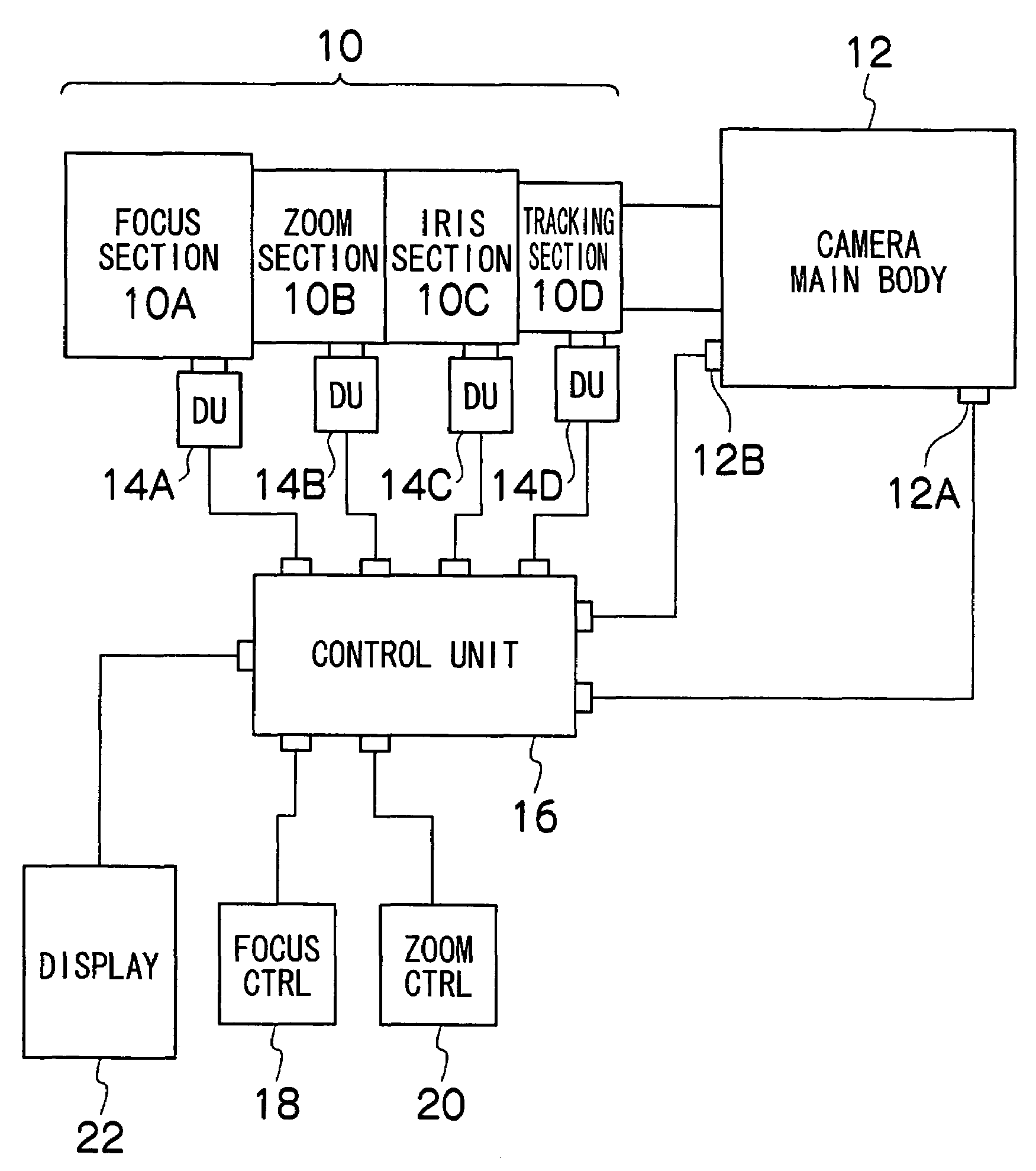
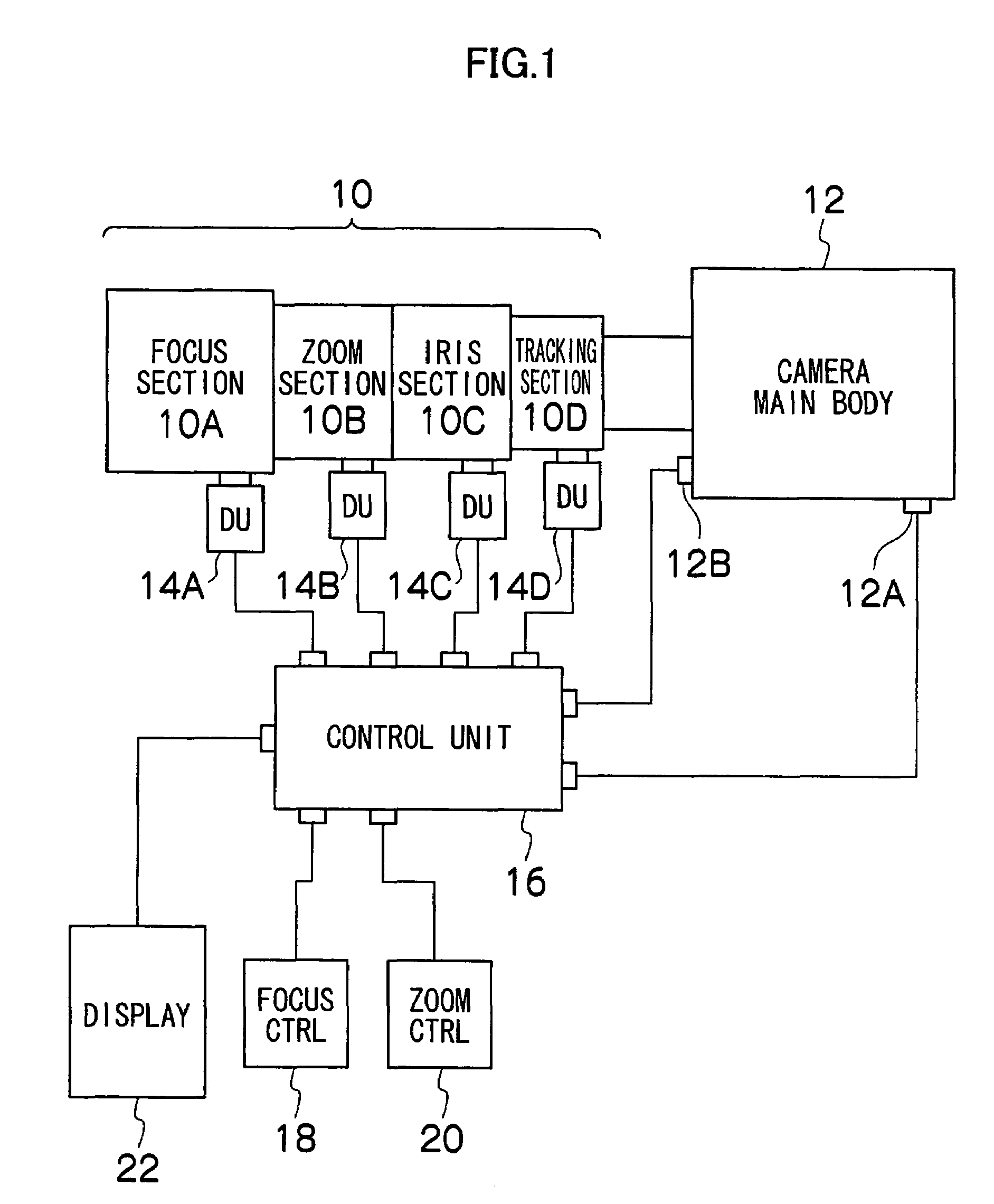
[0027]FIG. 1 is a block diagram showing the configuration of a photographing system for motion pictures to which the present invention is applied. The photographing system according to the present embodiment is suitable for film making.

[0028]In FIG. 1, a photographing lens (optical system) 10 is installed on a camera main body 12 using a mount, with a photographing element, a video signal processing circuit, and the like mounted on the camera main body. The photographing lens 10 is divided into a focus section 10A, a zoom section 10B, an iris section 10C, and a tracking section 10D in association with the types of movable optical parts arranged in a lens barrel. A group of focus lenses driven in the direction of an optical axis to focus on a subject are mainly arranged in the focus section 10A....

second embodiment

(Second Embodiment)

[0058]With reference to the drawings, a detailed description will be given of a preferred embodiment of a focus information display apparatus according to the present invention.

[0059]FIG. 6 is a control block diagram showing the whole configuration of a television lens system to which the present invention is applied. First, description will be given of the configuration schematically shown in FIG. 6 and used in the television lens system. For example, optical parts such as a zoom lens (group) ZL, a focus lens (group) FL, an extender lens (group) EL, an iris I are arranged in a photographing optical lens (photographing lens) of a lens apparatus 110. The lens apparatus 110 is provided with a zoom motor ZM, a focus motor FM, an extender motor EM, and an iris motor IM in association with these optical parts. The lens apparatus 110 is also provided with transmission mechanisms (gear trains) ZG, FG, EG, and IG which transmit power from the corresponding motors to the c...


PUM


Abstract

A screen of a display of a photographing system shows a distance scale indicating a present focus position and an indicator. The screen also shows a focus position already obtained by auto focusing, using a mark.

Description

BACKGROUND OF THE INVENTION[0001]1. Field of the Invention[0002]The present invention relates to a lens control system, and in particular, to a lens control system capable of auto focusing and manual focusing.[0003]The present invention also relates to a focus information display apparatus, and in particular, to a focus information display apparatus that displays a pre-stored desired focus position for reference during a focus operation.[0004]2. Description of the Related Art[0005]In general, in film making, manual focus operations are performed in order to intentionally perform focus operations during photographing and to reliably focus on a desired subject (refer to, for example, Japanese Patent Application Publication No. 63-287937). Furthermore, test photographing is carried out before actual photographing in order to check and set photographing conditions for a camera and a photographing lens. At this time, a focus position for the actual photographing is checked so as to be re...

Claims


Application Information

Patent Timeline
Patent Type & Authority Patents(United States)
IPC IPC(8): G03B13/34G02B7/28
CPCH04N5/23212G02B7/28H04N23/67H04N23/633
Inventor SASAKI, TADASHIKANEKO, KEIJIOUCHI, SYUNICHIRO
Owner FUJI PHOTO OPTICAL CO LTD
Why Eureka
Try Eureka