Intermediate image transfer device for a color image forming apparatus

a image transfer technology, applied in the field of intermediate image transfer type of color image forming apparatus, can solve the problems of lowering image transferability, irregular image transfer, and varying resistivity on the surface of the belt to which a bias is applied

Active Publication Date: 2006-02-21
RICOH KK
View PDF19 Cites 62 Cited by
  • Summary
  • Abstract
  • Description
  • Claims
  • Application Information

AI Technical Summary

Benefits of technology

[0017]It is a first object of the present invention to provide an image forming apparatus capable of obviating defective image transfe

Problems solved by technology

A problem with the intermediate image transfer type of image forming apparatus is that when image formation is repeated, image transferability is lowered or image transfer becomes irregular due to aging, as determined by experiments.
One cause of the above problem is that resistivity on the surface of the belt to which a bias is applied varies due to repeated image formation.
A change in the surface resistivity of the belt directly translates into a change in adequate bias and other image transfer conditions, lowering transferability or, when they locally vary, rendering image transfer irregular.
Consequently, if the surface resistivity of the surface applied with the bias is low, then a current easily flows on the surface of the belt and causes, if large in amount, nearby primary image transferring means to interfere with each other.
This also causes the problems discussed above to arise.
Another cause of low transferability and irregular image transfer ascribable to aging is that the volume resistivity of the belt decreases as image formation is repeated.
This also causes the image transfer conditions to vary as when the surface resistivity of the belt varies, bringing about the problems stated above.
It is known that the variation of resistance stated above occurs because the belt is subject to electric adverse influence, i.e., so-called hazard ascribable to, e.g., repeated bias application.
The bias control scheme, however, cannot obviate irregular image transfer because the resistance of the belt does not uniformly vary due to the influence of toner and sheet.
Further, a current flows al

Method used


Image

  • Intermediate image transfer device for a color image forming apparatus
  • Intermediate image transfer device for a color image forming apparatus
  • Intermediate image transfer device for a color image forming apparatus

Examples


example 1

[0115]The belt 10 was implemented as a belt whose surface potential, as measured at a position to which a primary image transfer bias V0 was applied, decreased to V0 / 2 or below in 5 seconds since the application of the bias. More specifically, a surface potential attenuation ratio, i.e., the ratio of charge remaining on the belt 10 in 5 seconds to the original charge was ½ or less. Let such residual charge left on the belt 10 in 5 seconds be referred to as a 5-second potential hereinafter.

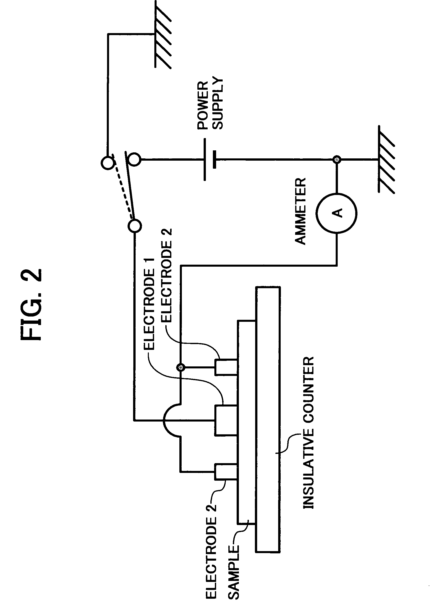
[0116]FIG. 16 shows a device used to measure the surface potential attenuation ratio of the belt 10. As shown, a probe is pressed against one surface of a belt or sample while a counter electrode, which is grounded, is held in contact with the other surface of the belt. For measurement, HYRESTER and URS mentioned earlier were used. A voltage of 100 V output from a high-tension power supply was applied via a switch at preselected timing. Subsequently, the switch is brought into connection with a sur...

example 2

[0124]Example 2 is practicable with the same copier configuration as Example 1. This is also true with the other examples to follow. The following description will therefore concentrate on configurations unique to Example 2.

[0125]In Example 2, a period of time in which the surface potential of the portion of the belt 10 applied with a primary image transfer bias V0 drops to V0 / 2 is determined to be T seconds, which is the interval between the preceding and following primary image transfer. More specifically, T seconds is the interval between the time when a black toner image, which is the last one of four toner images constituting a composite color image, is transferred to the belt 10 and the time when a yellow toner image, which is the first one of four toner images, is transferred to the belt 10 after the secondary transfer of the above composite toner image to a sheet. Let the potential remaining on the belt 10 in T seconds be referred to as T-second potential.

[0126]Experimental ...

example 3

[0130]In Example 3, the belt 10 is provided with surface resistivity of 107 Ω / □ or above, but 1012 Ω / □ or below, on the inner surface thereof to which the primary image transfer bias Vo is applied. Hereinafter will be described experimental results indicating a relation between the surface resistivity of the inner surface of the belt 10 and image quality.

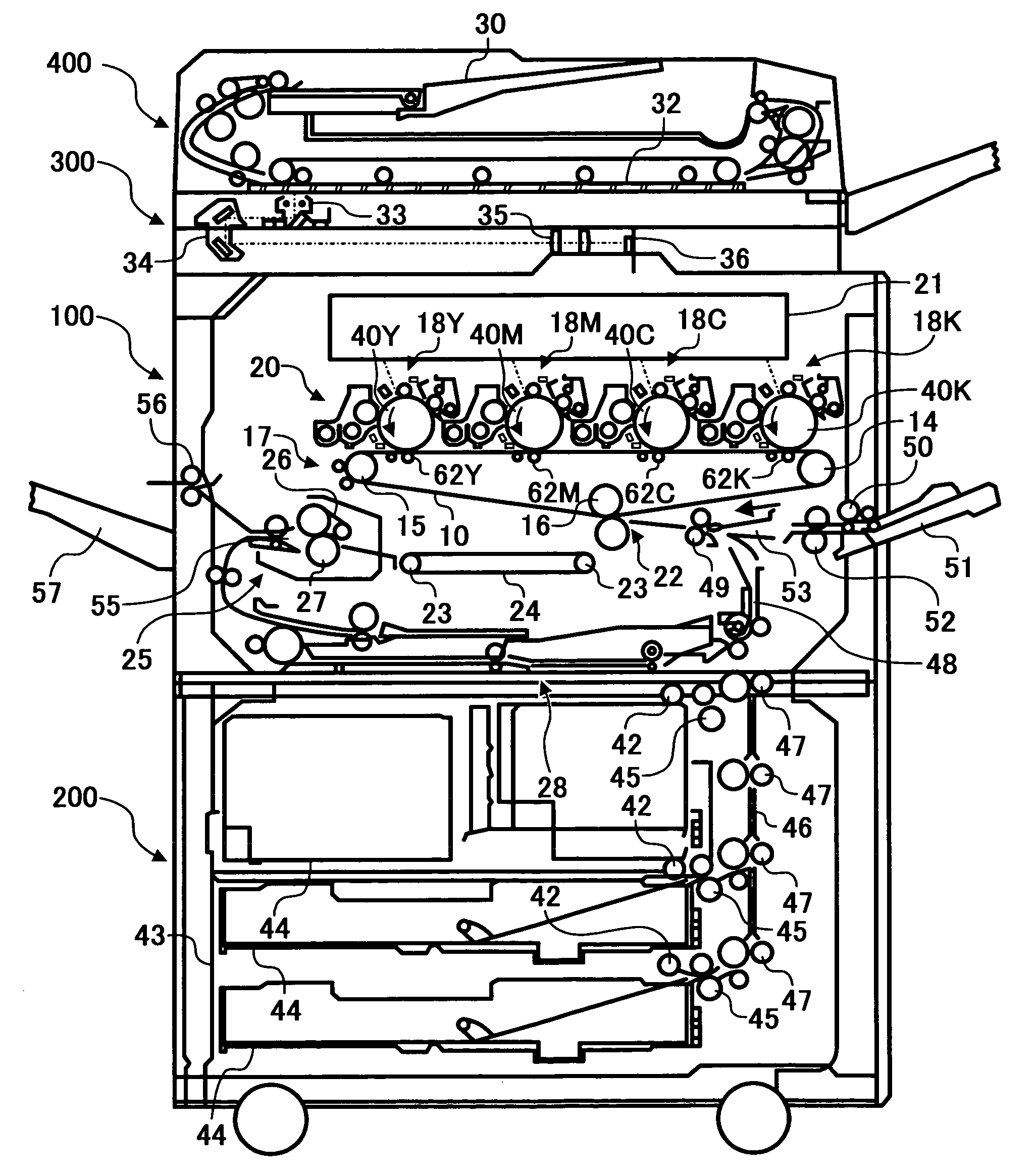
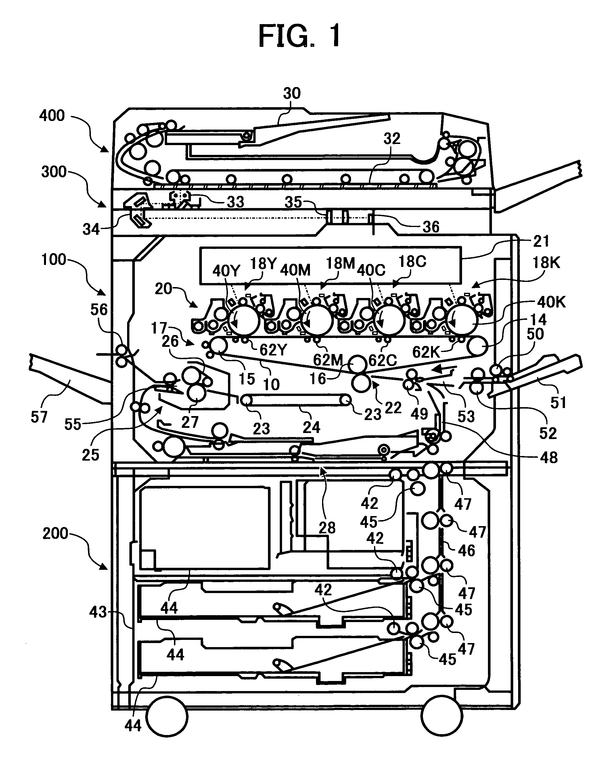
[0131]FIG. 19 shows the results of estimation effected with nine belts Nos. 7 through 15 each having particular surface resistivity by use of the copier shown in FIG. 1. More specifically, whether or not an image was defective was determined on the basis of an image transfer ratio and a discharge mark. Surface resistivity was measured by HYRESTER-UP mentioned earlier at temperature of 23° C. and humidity of 50%. The probe URS mentioned earlier was also used. The voltage applied was 500 V.

[0132]As FIG. 19 indicates, when the belt No. 7 with the surface resistivity of less than 1×10⁷ Ω / □ on the inner surface was used, the image transf...


PUM


Abstract

An intermediate image transfer type of image forming apparatus of the present invention includes an image carrier, an intermediate image transfer body, primary image transferring means for transferring a toner image from the image carrier to the intermediate image transfer body, and secondary image transferring means for transferring the toner image from the intermediate image transfer body to a sheet. When the surface resistivity of the intermediate image transfer body is measured by a method that repeatedly applies a voltage of 200 V for 60 seconds to the intermediate image transfer body and grounds the intermediate image transfer body for 10 seconds 1,000 consecutive times, a difference in absolute value between the logarithm of the first time of measurement and that of the thousandth time of measurement is 0.5 log Ω/□ or below.

Description

BACKGROUND OF THE INVENTION[0001]1. Field of the Invention[0002]The present invention relates to a copier, facsimile apparatus, printer or similar image forming apparatus and more particularly to an intermediate image transfer type of color image forming apparatus.[0003]2. Description of the Background Art[0004]Generally, an intermediate image transfer type of image forming apparatus includes an image carrier, an intermediate image transfer body, primary image transferring means for transferring a toner image from the image carrier to the intermediate image transfer body, and secondary image transferring means for transferring the toner image from the intermediate image transfer body to a sheet or similar recording medium. This type of image forming apparatus is disclosed in, e.g., Japanese Patent Laid-Open Publication No. 2002-214932. The image carrier, configured to carry a toner image corresponding to image data, is implemented as a photoconductive drum by way of example. For the...

Claims


Application Information

Patent Timeline
IPC IPC(8): G03G15/01G03G15/16
CPCG03G15/1605G03G2215/0119G03G2215/0164
Inventor YOSHIDA, KENSAWAI, YUUJIOGIYAMA, HIROMITAKEHARA, ATSUSHIKAYAHARA, SHINKATO, SHINJIFUJIWARA, YOSHIHIRO
Owner RICOH KK
Why Eureka
Try Eureka