Fuel treatment device using a magnetic field

a fuel treatment device and magnetic field technology, applied in the direction of combustion-air/fuel-air treatment, separation process, filtration separation, etc., can solve the problems of clogging the fuel filter, reducing the filterability and clean combustion of diesel fuel and gas-oil, and agglomerating organic compounds, so as to improve the combustion and filterability of fuel and reduce the effect of clustering

Active Publication Date: 2006-02-28
AXI INT CORP
View PDF61 Cites 7 Cited by
  • Summary
  • Abstract
  • Description
  • Claims
  • Application Information

AI Technical Summary

Benefits of technology

[0004]Magnetic field flux density varies depending on the magnetic material used, the shape of the magnet, the positioning of the poles, and proximity to the poles. At the atomic level, inductive forces are transmitted to a fluid passing through magnetic flux, producing an orientation effect on polar molecules in the fuel, and thus discourages clustering of paraffins and other long chain molecules, allowing them, as a consequence, to stay in suspension and thus bum more completely. The strength of this effect depends on the direction of fluid flow relative to flux lines, as well as velocity of flow and magnetic flux density. Research and field trials conducted by the inventor have shown that fuel channel design can be altered to optimize the orientation effect beyond that of current treatment devices, thereby producing unexpected improvements in fuel combustion and filterability.

Problems solved by technology

Such instability results in polymerization and agglomerations of organic compounds that reduce filterability and clean combustion of diesel fuels and gas-oil.
As these clusters of large molecules increase in size, they clog fuel filters and can eventually contribute to sludge in fuel storage tanks.
Even though results have shown some improvement in fuel filterability, current methods have not been able to address the larger issues of fuel stability.

Method used


Image

  • Fuel treatment device using a magnetic field
  • Fuel treatment device using a magnetic field
  • Fuel treatment device using a magnetic field

Examples


Embodiment Construction

[0020]The present invention is directed to a fuel treatment device, in particular a fuel treatment device that utilizes a magnetic field effective in improving combustion and filterability of conventional petroleum-based hydrocarbon fuels (i.e. fossil fuels).

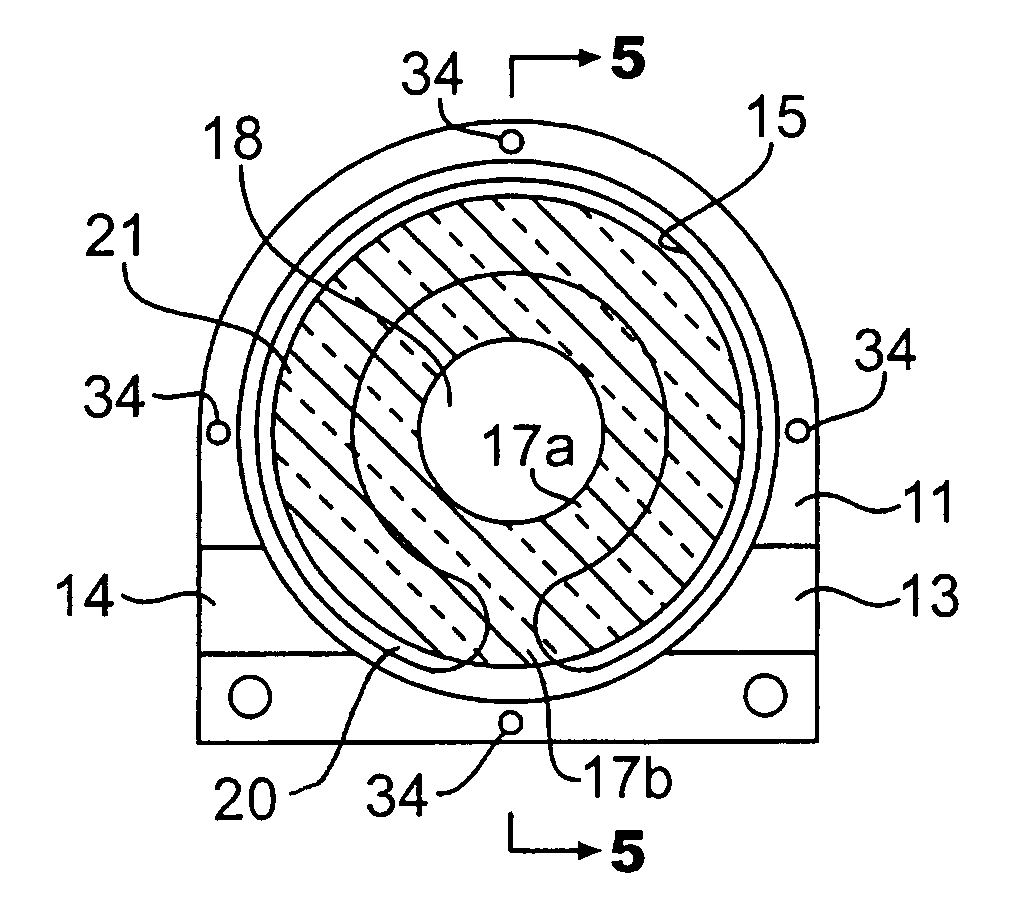
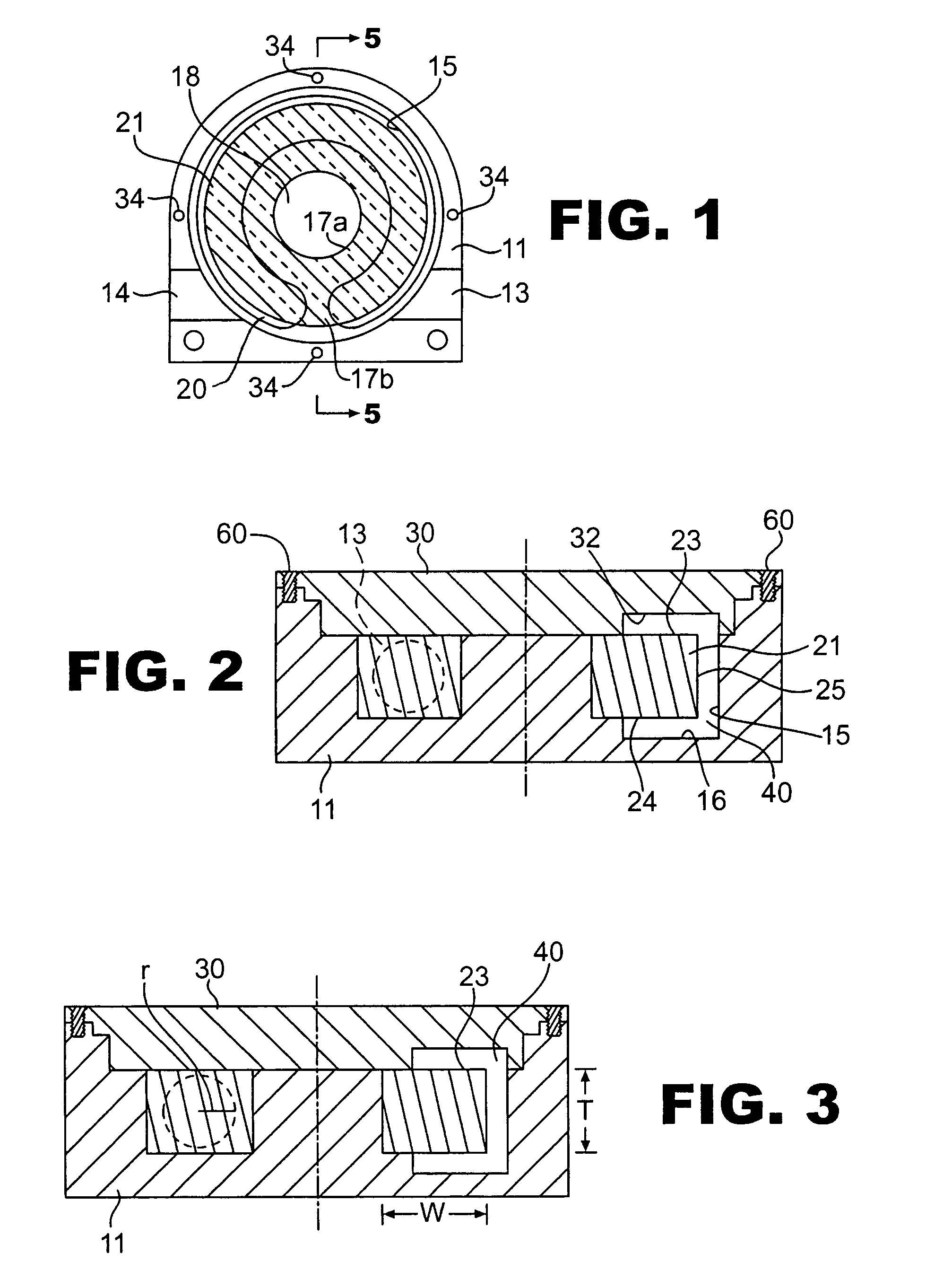
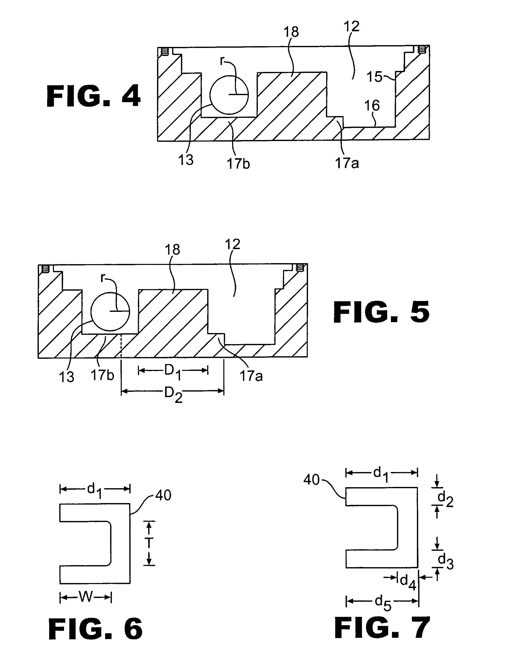
[0021]Referring now to the figures, the invention in certain aspects comprises a fuel treatment device 10 comprising a housing 11, the housing further having an inner compartment 12. The housing 11 also has a fuel entry port 13 and a fuel exit port 14, which in the embodiments illustrated in the figures, are in registration with one another. When the device is installed within a fuel line, the fuel line is split so that it may be connected to the fuel entry and exit ports. FIG. 1 illustrates the fuel entry port 13, for example, as being positioned on the right side of the housing; however, it will be appreciated by the skilled artisan that these fuel ports may be reversed (i.e. the entry port may be where the exit port 14 is sho...


PUM

PropertyMeasurementUnit
magnetic fieldaaaaaaaaaa
velocityaaaaaaaaaa
velocityaaaaaaaaaa

Abstract

Magnetic fuel treatment devices are disclosed, the devices comprising, in part, a housing, cover, inner compartment, and magnet, the combination of which forming an inner fuel channel through which fuel may flow for treatment therein. Certain aspects of the invention include designs that concentrate fuel flow within magnetic flux densities ranging from about 600 to about 1,200 Gauss.

Description

BACKGROUND AND SUMMARY OF THE INVENTION[0001]Refining methods employed in the late 20th and early 21st centuries produce hydrocarbon fuels and oils that are unstable. Such instability results in polymerization and agglomerations of organic compounds that reduce filterability and clean combustion of diesel fuels and gas-oil. In the case of hydrocarbon fuels, asphaltenes (precursors to heavy hydrocarbon oils) and resins have mechanical affinity for each other and thereby have a tendency to form flocculations or aggregations. As these clusters of large molecules increase in size, they clog fuel filters and can eventually contribute to sludge in fuel storage tanks.[0002]Fuel treatment methods have worked from the premise that filterability problems with diesel fuel were largely due to “bio-fouling” (i.e. microbial activity from fungus, yeast, mold, and aerobic or anaerobic sulfur-reducing bacteria). Although microbial activity plays a role in the deterioration of fuel quality and may co...

Claims


Application Information

Patent Timeline
Patent Type & Authority Patents(United States)
IPC IPC(8): F02B75/10F02M27/04
CPCF02M27/045
Inventor LISSEVELD, WOUT
Owner AXI INT CORP
Why Eureka
Try Eureka