Fiber reinforced soil stirring device and stirring method

A technology of fiber reinforced soil and stirring device, which is applied in the directions of mixing methods, mixer accessories, chemical instruments and methods, etc. problem, to eliminate the interference of artificial factors, strengthen the stirring effect, and avoid the effect of static electricity

Active Publication Date: 2017-02-01
HOHAI UNIV
View PDF3 Cites 2 Cited by
  • Summary
  • Abstract
  • Description
  • Claims
  • Application Information

AI Technical Summary

Problems solved by technology

[0003] For the fibers that are often studied and used in the above fiber reinforced soil technology, natural fibers are easy to obtain, but they have insufficient environmental erosion resistance and durability, and the fiber parameters (length, diameter, strength, etc.) are highly discrete. , it is difficult to uniformly control, so artificial synthetic fibers will be the key research and application objects in this field in the future
However, according to the existing research results, although artificial synthetic fibers have many incomparable advantages over natural fibers, they also have the disadvantage of being prone to electrostatic interactions.
And when the fiber content is larger, the electrostatic effect of the fiber in the soil will be more obvious, and the phenomenon of clustering will be more, which will make it difficult for the fiber to mix evenly in the soil, and even create a weak area, which makes the The mechanical properties of soil are close to the original intention of isotropy
At the same time, this shortcoming will not only greatly reduce the reinforcement effect of fiber reinforcement, but also hinder the development of the constitutive relationship and design theory of fiber reinforced soil.
Therefore, for this kind of fiber-reinforced soil, there is still a lack of a special mixing device with simple structure and easy operation to solve the problem that synthetic fibers are difficult to mix evenly in the soil due to static electricity.

Method used


Image

  • Fiber reinforced soil stirring device and stirring method
  • Fiber reinforced soil stirring device and stirring method
  • Fiber reinforced soil stirring device and stirring method

Examples


Embodiment

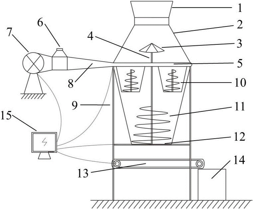
[0028] The fiber reinforced soil stirring device of the present embodiment is as figure 1 As shown, it includes: crushing soil bin 1, soil splitting bin 2, soil splitting turntable 3, soil splitting shaft 4, fiber ring tube 5, fiber bin 6, tuyere 7, fiber channel 8, bracket 9, small mixing bin 10, Large mixing bin 11, large mixing bin bottom plate 12, transmission crawler belt 13, unearthed bin 14 and computer control host 15. The broken soil bin 1 and the divided soil bin 2 are separated by a base plate.

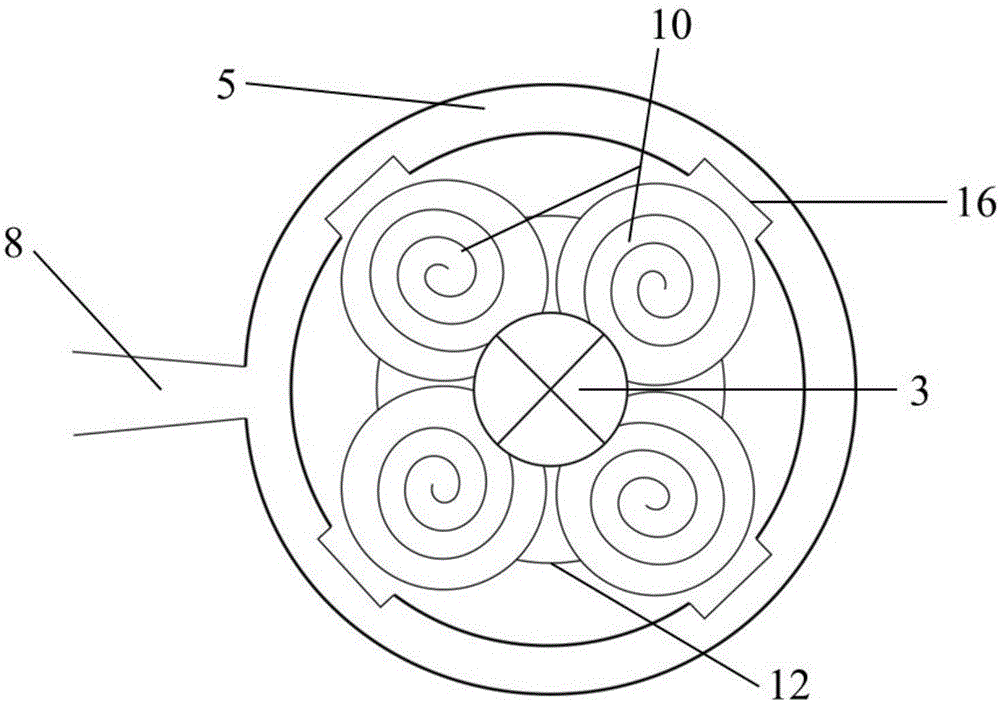
[0029] Wherein, the top view of sub-soil bin 2 is as follows: figure 2 As shown, the fiber channel 8 communicates with the fiber ring pipe 5, and at the center of the fiber ring pipe 5 facing the small mixing chamber, there is a strip-shaped fiber ring pipe outlet 16, and the top of the small mixing chamber 10 has a soil dividing turntable 3 , There is a large mixing bin bottom plate 12 below. Using the fiber-reinforced soil mixing device of the present embodiment, when...


PUM


Abstract

The invention discloses a fiber reinforced soil stirring device and a stirring method. The device comprises a feeding unit, a distributing unit, a stirring unit, a discharging unit and a computer control unit. The device sets relevant parameters through bundled software, and automatic control over the stirring and discharging processes is achieved. The stirring method of the stirring device includes the steps that chopped fiber filaments are in a suspended state through wind pressure, the chopped fiber filaments make contact with continuously-falling soil materials in the air, fiber mixed soil materials enter partition bins to be stirred, and finally the materials are stirred through the partition bins and then enter a large bin in a centralized mode to be stirred, therefore, the phenomenon of gathering into clusters generated due to the static effect of fiber filaments is avoided, and the stirring uniformity of fibers and the soil materials is enhanced.

Description

technical field [0001] The invention relates to the field of soil reinforcement and improvement, in particular to a fiber reinforced soil stirring device and a stirring method. Background technique [0002] Fiber reinforcement technology is a new type of soil improvement technology developed in the field of geotechnical engineering in recent years. It specifically refers to the uniform mixing of dispersed fiber filaments into the soil to achieve the purpose of improving the properties of soil engineering. Compared with traditional soil reinforcement and improvement methods, the advantage of fiber reinforcement technology is that the degree of dispersion of fibers in the soil is relatively high, which can make the mechanical properties of the reinforced soil close to isotropy, and can obtain chemical additives ( Such as cement, lime, etc.), can also make up for the weak surface of reinforced soil of traditional geosynthetics (such as geotextiles, geogrids, etc.). At present,...

Claims


Application Information

Patent Timeline
Patent Type & Authority Applications(China)
IPC IPC(8): B01F13/10B01F15/02B01F3/18
CPCB01F23/69B01F33/81B01F33/8361B01F35/7545
Inventor 高磊胡国辉龚云皓胡艳杰杨凯
Owner HOHAI UNIV
Why Eureka
Try Eureka