Single unit protection circuit module and battery pack using the same

a protection circuit module and battery pack technology, applied in the direction of safety/protection circuits, secondary cells servicing/maintenance, electrochemical generators, etc., can solve the problems of increasing increasing the length and width of printed circuit boards, and limiting the capacity of secondary batteries, so as to increase the probability of soldering defects. , the effect of increasing the probability

Active Publication Date: 2007-09-27
SAMSUNG SDI CO LTD
View PDF6 Cites 22 Cited by
  • Summary
  • Abstract
  • Description
  • Claims
  • Application Information

AI Technical Summary

Benefits of technology

[0012]Further, in the related art related art protection circuit module and the battery pack, the number of main parts to be soldered to the printed circuit board is 3, and requires at least 3 times of soldering to be performed. Accordingly, the number of steps in the work to make the related art printed circuit board and the probability of soldering defects increases.
[0013]Further, in the related art protection circuit module and the battery pack, a separate wiring pattern needs to be formed on the printed circuit board in order to couple the integrated circuit with the two switches. Hence, an additional wiring-pattern-forming process on the printed circuit board is necessary. The wiring-patterns increase the probability that an external static electricity or the electromagnetic wave will flow into the integrated circuit and the two switches. Further, there is a risk of the static electricity or the electromagnetic causing erroneous operation of the related art protection circuit module and the battery pack.
[0014]Further, in the related art protection circuit module and the battery pack, a separate capacitor to prevent static electricity needs to be electrically coupled to the two switches in parallel, and a separate resistor to prevent static electricity needs to be electrically coupled to the wiring that controls the two switches.

Problems solved by technology

Thus, the length and the width of the printed circuit board increases due to the individual semiconductor packages, which is disadvantageous.
Accordingly, such limits the capacity of the secondary battery.
Accordingly, the number of steps in the work to make the related art printed circuit board and the probability of soldering defects increases.
Further, there is a risk of the static electricity or the electromagnetic causing erroneous operation of the related art protection circuit module and the battery pack.

Method used


Image

  • Single unit protection circuit module and battery pack using the same
  • Single unit protection circuit module and battery pack using the same
  • Single unit protection circuit module and battery pack using the same

Examples


Embodiment Construction

[0043]Reference will now be made in detail to aspects of the present invention, examples of which are illustrated in the accompanying drawings, wherein like reference numerals refer to the like elements throughout. The aspects are described below in order to explain the present invention by referring to the figures.

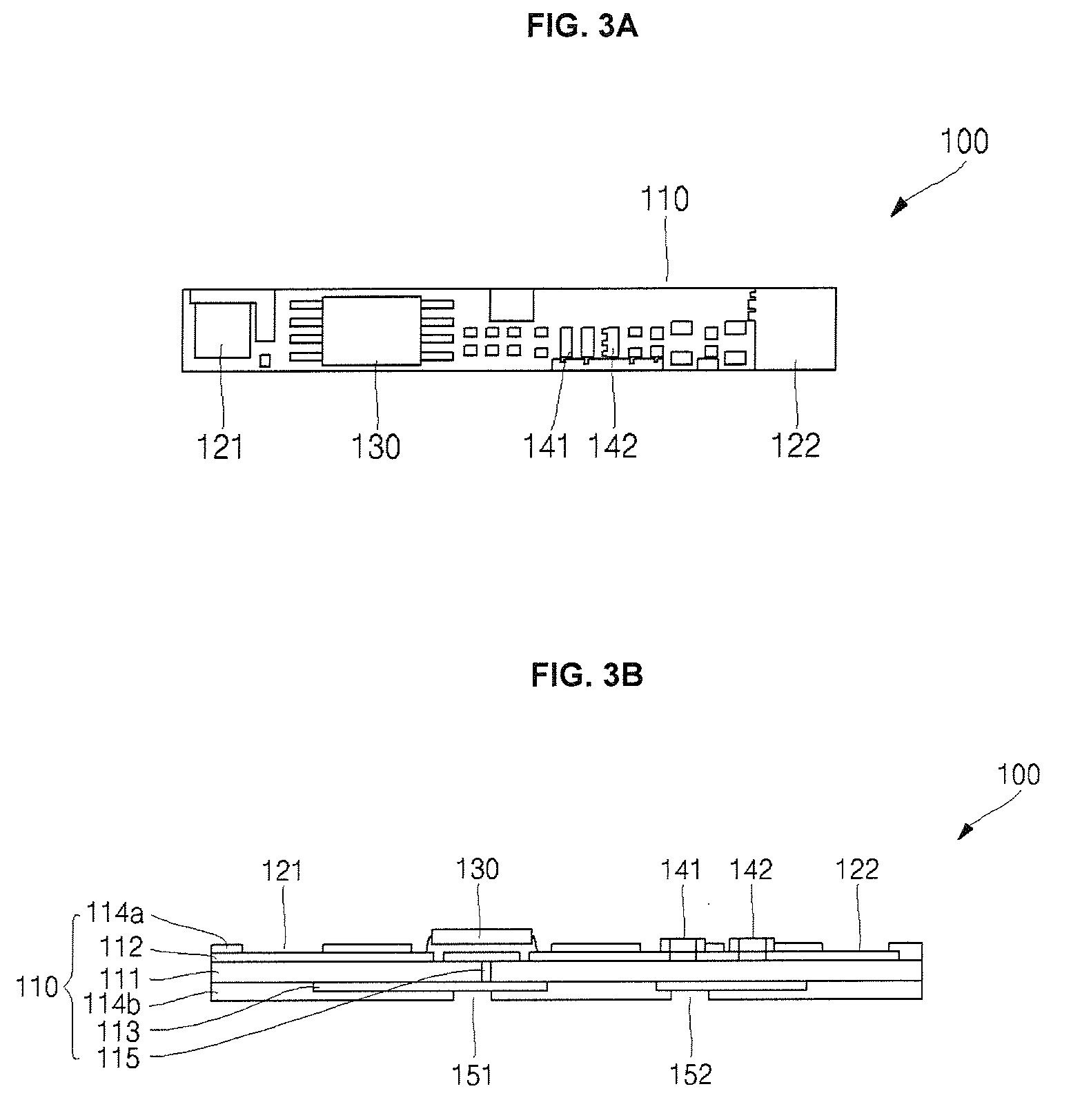
[0044]FIGS. 3A and 3B illustrate a protection circuit module 100 according to an aspect of the present invention. As illustrated, a protection circuit module 100 includes a printed circuit board 110, conductive pads 121 and 122 formed on one side of the printed circuit board 110, a semiconductor package 130 soldered on one side of the printed circuit board 110, a plurality of passive elements 141 and 142 soldered on the printed circuit board 110, and pack terminals 151 and 152 formed on the printed circuit board 110.

[0045]In the aspect shown, a plurality of wiring patterns 112 and 113 are formed on the upper side (or a first side) and the lower side (or a second side) of ...


PUM

PropertyMeasurementUnit
charging voltageaaaaaaaaaa
discharging voltageaaaaaaaaaa

Abstract

A protection circuit module includes a printed circuit board in which at least one wiring pattern is formed, a conductive pad that is coupled to a wiring pattern of the printed circuit board, and is electrically coupled to a rechargeable battery, and a semiconductor package that is soldered on the wiring pattern of the printed circuit board, so that if the voltage of the rechargeable battery is in the overcharged or over-discharged state, the semiconductor package selectively blocks a charging path or a discharging path of the rechargeable battery.

Description

CROSS-REFERENCE TO RELATED APPLICATION[0001]This application claims priority to Korean Patent Application No. 2006-27525, filed on Mar. 27, 2006 in the Korean Intellectual Property Office, the disclosure of which is incorporated herein by reference.BACKGROUND OF THE INVENTION[0002]1. Field of the Invention[0003]Aspects of the present invention relate to a protection circuit module and a battery pack using the same, and more particularly, to a protection circuit module and a battery pack using the same having a small printed circuit board area, being resistant to electromagnetic waves or static electricity, and having reduced cost achieved by integrating an integrated circuit (IC), a charging switch, and a discharging switch in one semiconductor package.[0004]2. Description of the Related Art[0005]In general, lithium-type secondary batteries are high in energy density when compared with those of conventional nickel-cadmium and nickel-hydride batteries. Examples of lithium-type second...

Claims


Application Information

Patent Timeline
Patent Type & Authority Applications(United States)
IPC IPC(8): H02J7/00H01M10/052H01M10/36
CPCH01M10/052H01M10/425H01M10/44H05K2201/10689H05K1/0254H05K2201/10053H02J7/0031H01L2224/32245H01L2224/48091H01L2224/48137H01L2224/48247H01L2224/49111H01L2224/73265H01L2924/13091Y02E60/10H01L2924/00014H01L2924/00H02H9/04H02J7/00
Inventor KIM, YOUNGUKIM, BONG YOUNG
Owner SAMSUNG SDI CO LTD
Why Eureka
Try Eureka