Compact creel

a compact, creel technology, applied in the direction of tufting apparatus, thin material processing, textiles and paper, etc., can solve the problems of large space requirement, significant work required to prepare the beam, and substantial space within the carpet production facility, so as to reduce the amount of material handling, reduce the amount of slack ends, and improve the quality of finished products

Inactive Publication Date: 2006-02-28
INTERFACE INC
View PDF16 Cites 14 Cited by
  • Summary
  • Abstract
  • Description
  • Claims
  • Application Information

AI Technical Summary

Benefits of technology

[0013]To provide a compact creel that reduces yarn waste in the tufting, production and warping processes.
[0015]To provide a compact creel that increases the quality of the finished product by reducing slack ends.
[0016]To provide yarn inventory reduction and decreased amounts of material handling.
[0017]To provide a compact creel that requires less floor space.
[0019]To provide a compact creel that reduces the labor required in the warping process.

Problems solved by technology

However, substantial space within a carpet production facility is required for the entire tufting process.
While beams typically require substantially less space immediately in front of the tufter than conventional creels, substantial space is needed, and significant work is required to prepare the beam, because in order to position yarn on a beam, bobbins or yarn packages must be positioned on creels to “feed” the beam, much as the yarn packages would be positioned to feed a tufter directly.
A significant challenge to carpet manufacturers is to reduce the amount of yarn waste occurring in the manufacturing of carpet.
For example, there can be yarn waste due to tufting beam waste, production beam waste and / or warping beam waste.
A cause of waste is the inability to effectively determine the amount of yarn that is needed for a particular piece of carpet.
As yarn is fed into a tufting machine it may be realized that yarn length for one color in a pattern is too short while yarn length for another color in the pattern is too long, resulting in wasted yarn.
Large bobbins of yarn or beams of yarn compound the problem due to the sheer size of the yarn contained.
Another significant problem is carpet overrun overage.

Method used


Image

  • Compact creel
  • Compact creel
  • Compact creel

Examples


Embodiment Construction

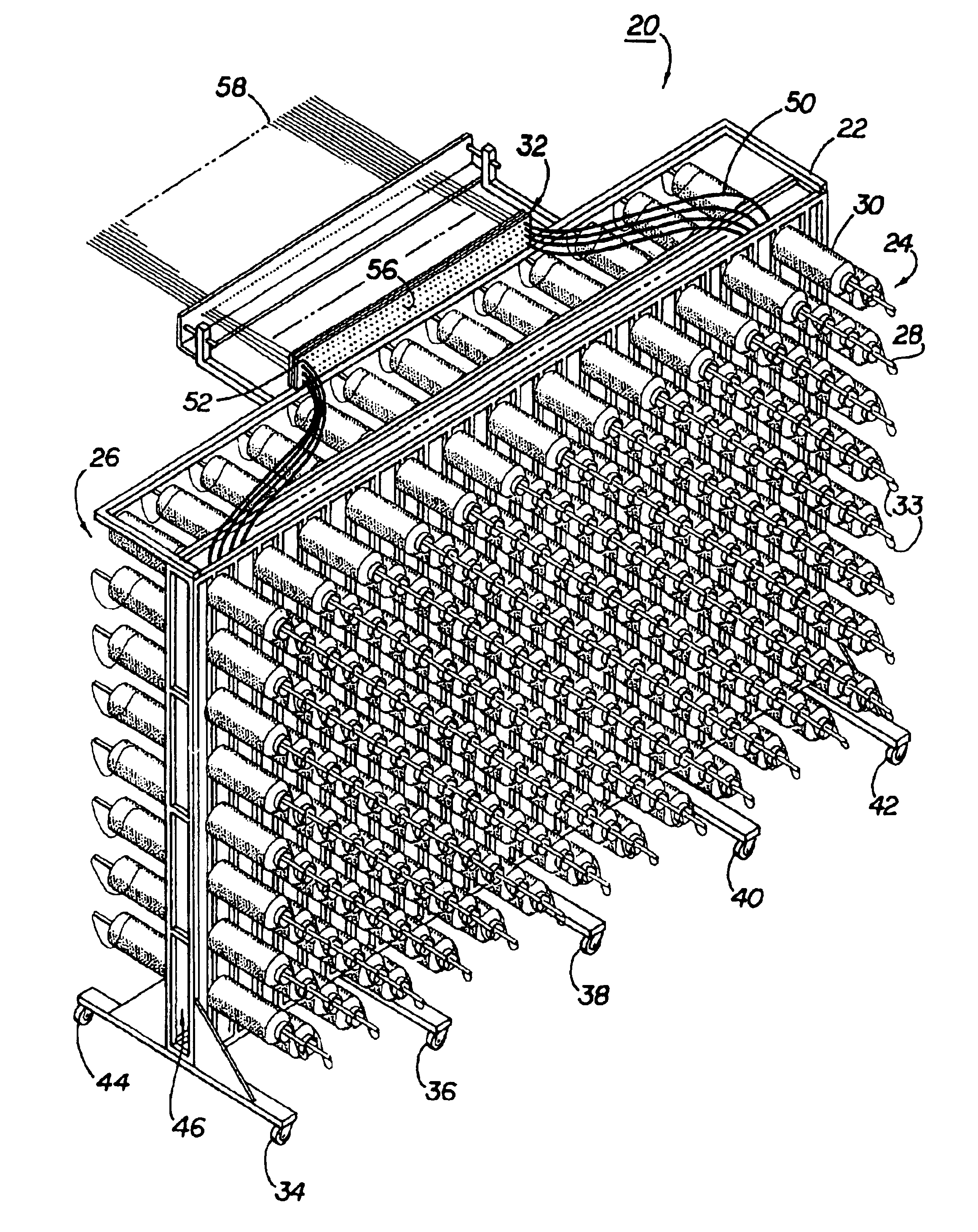
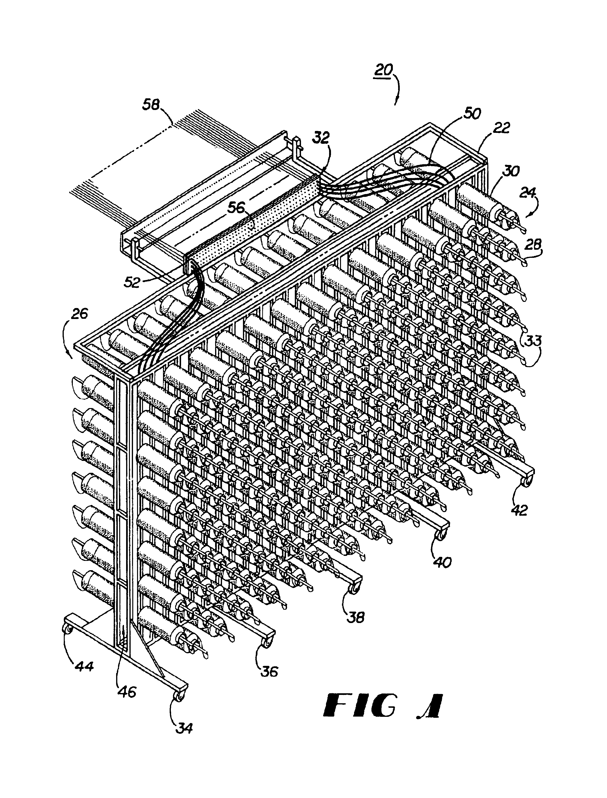
[0033]FIG. 1 is a perspective view of a compact creel 20 of this invention. The compact creel 20 includes a frame 22 having a front portion 24 and a rear portion 26, multiple hollow supports 28 attached to the frame 22 for holding yarn packages 30, and an attachable header 32. Preferably, the frame 22 can hold about 832 yarn packages 30 with approximately 416 yarn packages 30 on each of the front 24 and rear 26 portions of a sixteen foot frame 22. Generally, the yarn packages 30 have a diameter of about seven inches and are about twelve inches long. Preferably, the overall footprint of the compact creel 20 is on the order of 160 square feet or less. A variety of yarn packages 30 can be used with the compact creel 20 including yarn packages 30 containing yarn 33, that is for instance, tightly twisted, loosely twisted and air entangled. Casters 34, 36, 38, 40, 42 and 44 placed on the bottom of the frame 22 provide for ease of movement of the compact creel 20.

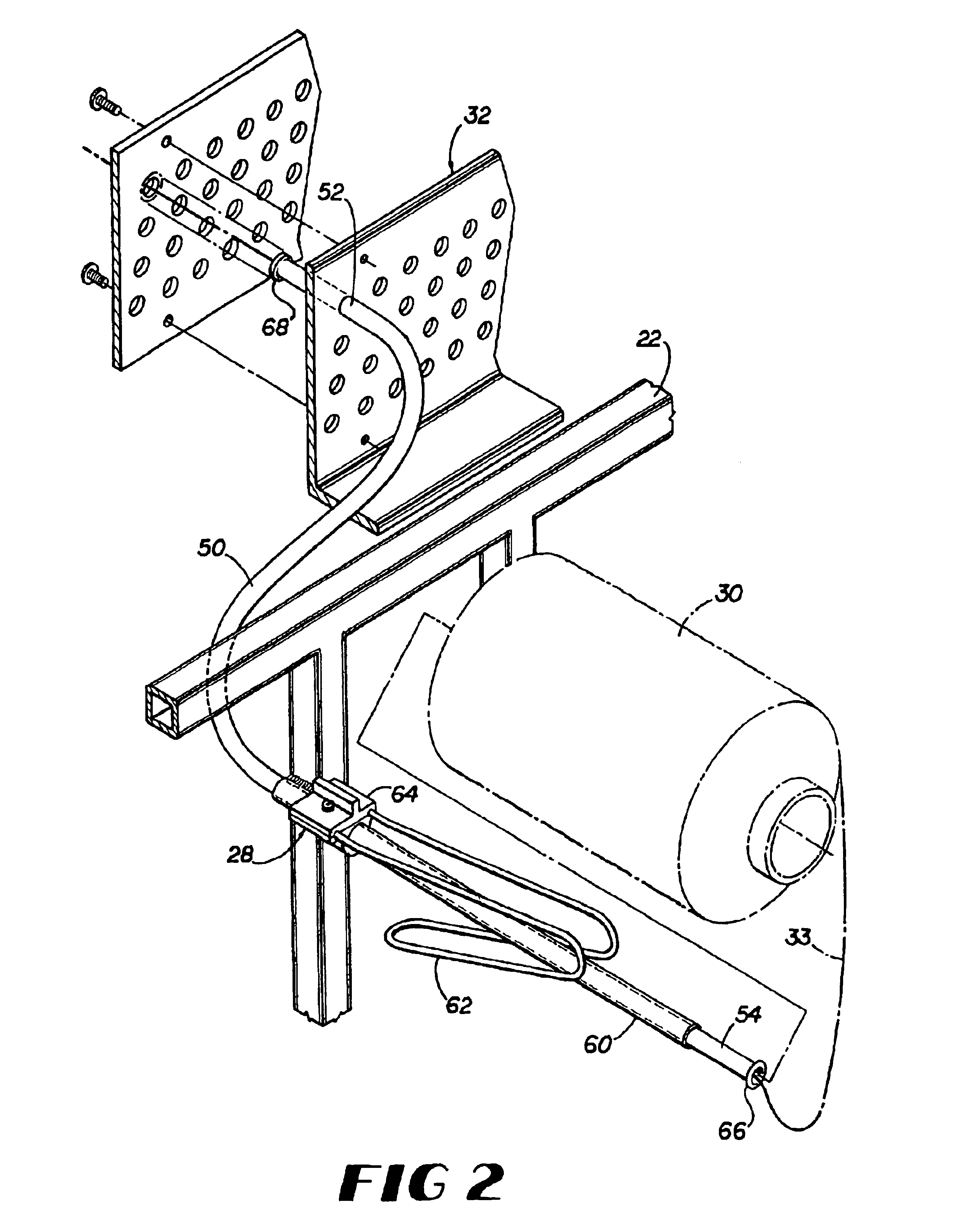
[0034]As illustrated in FI...


PUM

PropertyMeasurementUnit
diameteraaaaaaaaaa
sizesaaaaaaaaaa
diameteraaaaaaaaaa

Abstract

A highly mobile, compact creel that utilizes frames for holding yarn packages (or bobbins) for feeding yarn to a tufting machine. Each frame includes holders affixed to the frame for holding yarn packages facing front and back, a header attachable to the frame for directing yarn from the yarn packages to the tufting machine, and anti-static flexible tubing for leading yarn from the holders to the header. The header provides for aligning all the yarn ends in the same plane to join them to ends already threaded into the tufting machine. An optional frame overlay upright having a ring affixed thereto and strands threaded through the ring prevents yarn from upper yarn packages from falling onto tubes holding lower yarn packages causing yarn entanglement.

Description

RELATED APPLICATIONS[0001]This application is a continuation and claims priority to U.S. patent application Ser. No. 09 / 830,733 filed Jul. 23, 2001 now U.S. Pat. No. 6,634,585, PCT / US99 / 25985 filed Nov. 4, 1999 published as WO 00 / 27532, 60 / 107,494 filed Nov. 6, 1998, entitled, “Compressed Portable Tufting Creel,” U.S. Patent Application No. 60 / 107,495 filed Nov. 6, 1998, entitled, “Alignment Header for Burning-In Process,” and U.S. Patent Application No. 60 / 134,589 filed May 17, 1999, entitled, “Compact Creel,” all which are incorporated by reference herein.FIELD OF THE INVENTION[0002]This invention relates in general to the field of carpet production, and in particular, to carpet yarn creels.BACKGROUND OF THE INVENTION[0003]Carpet tufting machines are relatively compact devices. However, substantial space within a carpet production facility is required for the entire tufting process. In addition to the space occupied by a tufting machine (i.e. the tufter) itself, there must be roll...

Claims


Application Information

Patent Timeline
Patent Type & Authority Patents(United States)
IPC IPC(8): B65H49/02B65H57/00B65H49/16B65H57/12B65H57/16B65H63/06D02H1/00D05C15/16D05C15/18
CPCB65H49/16B65H57/003D05C15/18B65H57/16B65H57/12B65H2701/31
Inventor INGRAM, III, WILLIAM O.
Owner INTERFACE INC
Why Eureka
Try Eureka