Flow dam design for labyrinth seals to promote rotor stability

a flow dam and labyrinth seal technology, applied in mechanical devices, machines/engines, liquid fuel engines, etc., can solve the problems of monotonic swirl increase, exceed acceptable turbine vibration amplitude limits, and limitation may not, in some applications, sufficiently reduce the swirl effect of steam

Inactive Publication Date: 2006-02-28
SIEMENS ENERGY INC
View PDF19 Cites 30 Cited by
  • Summary
  • Abstract
  • Description
  • Claims
  • Application Information

AI Technical Summary

Problems solved by technology

The rotor whirl increase is monotonic with increasing turbine load, and can eventually exceed acceptable turbine vibration amplitude limits, requiring the operator to reduce the turbine load.
This limitation may not, in some applications, sufficiently reduce the steam swirl, as the swirl reduction is directly dependent on the number of flow dams disposed around the shaft circumference.

Method used


Image

  • Flow dam design for labyrinth seals to promote rotor stability
  • Flow dam design for labyrinth seals to promote rotor stability
  • Flow dam design for labyrinth seals to promote rotor stability

Examples


Embodiment Construction

[0035]Before describing in detail the particular seal ring system and method in accordance with the present invention, it should be observed that the present invention resides primarily in a novel and non-obvious combination of hardware elements and method steps. Accordingly, these elements and steps have been represented by conventional elements and steps in the drawings, showing only those specific details that are pertinent to the present invention so as not to obscure the disclosure with details that will be readily apparent to those skilled in the art having the benefit of the description herein.

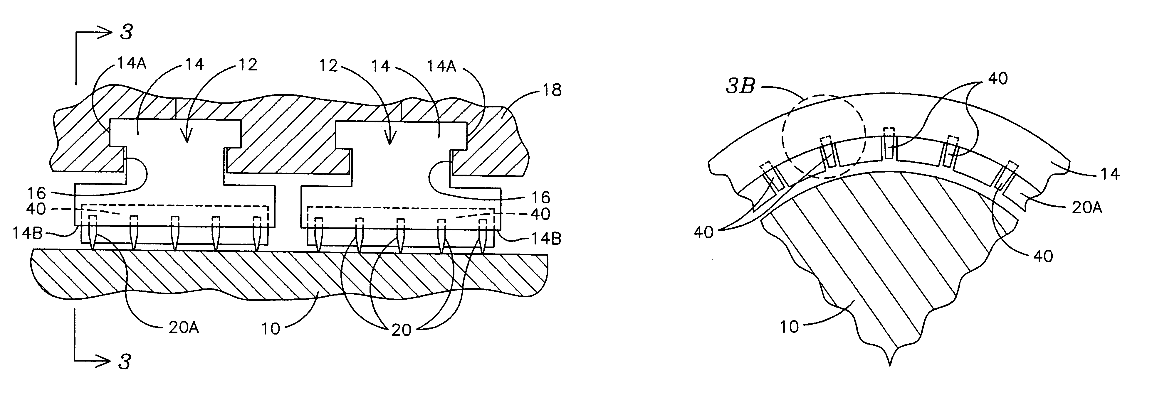
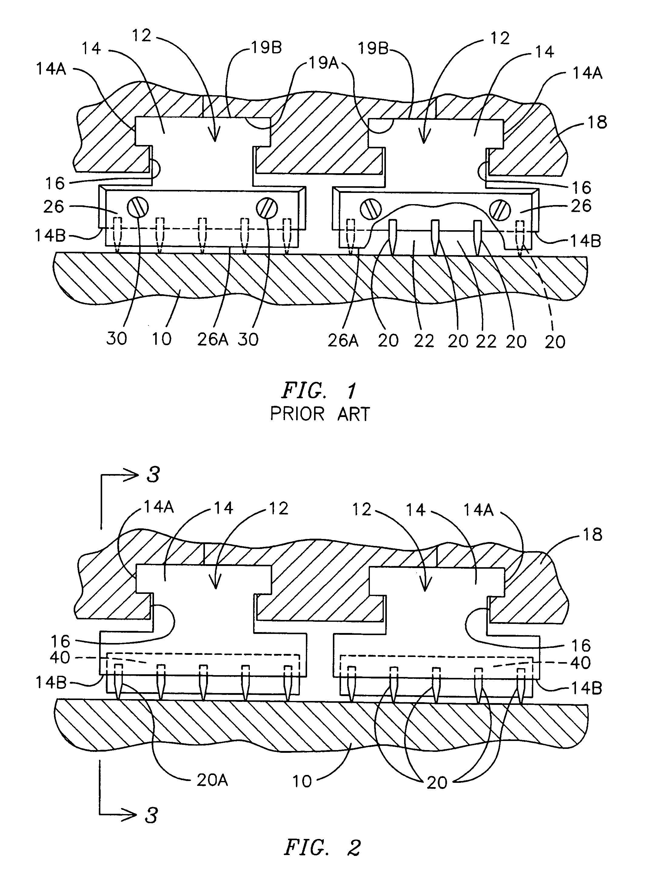
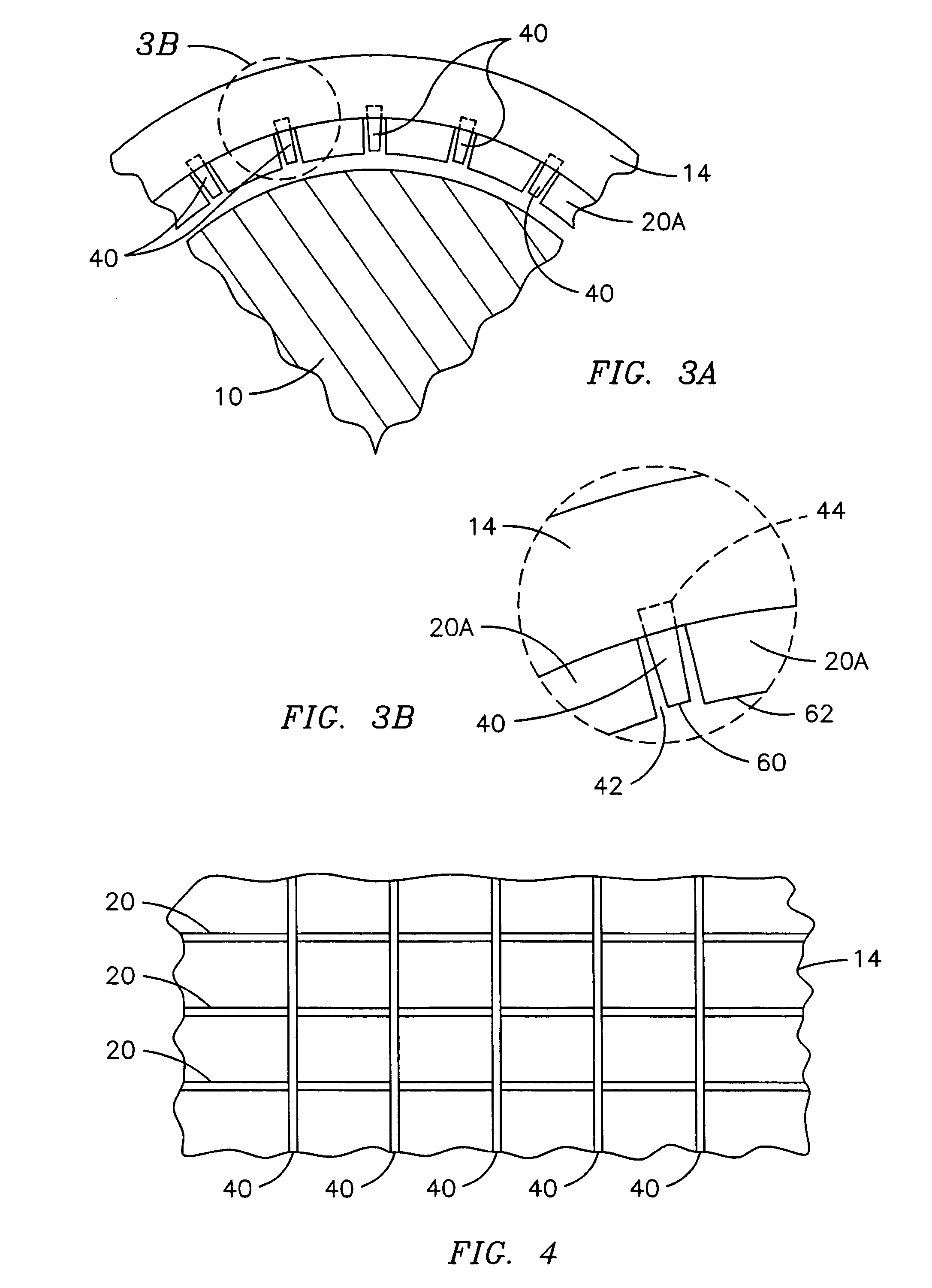
[0036]It is therefore desirable to provide a method and apparatus for further minimizing steam whirl in turbines by permitting placement of the flow dams at any desired circumferential location. According to the teachings of the present invention, flow dams 40 (see FIG. 2) can be installed at a plurality of circumferentially spaced-apart locations surrounding the shaft 10 by retaining t...


PUM


Abstract

A method and apparatus for reducing steam swirl in a steam turbine. A plurality of seal segments (14) are circumferentially juxtaposed to form a seal ring (12) encircling the turbine shaft (10), each seal segment (14) supporting a plurality of circumferentially disposed annular seal fins (20) to limit axial steam flow along the shaft (10). A plurality of flow dams (40) are disposed within grooves (42) defined in the plurality of seal fins (20) and seal segments (14) for limiting circumferential steam flow and thereby reducing rotor instability.

Description

FIELD OF THE INVENTION[0001]This invention relates generally to a sealing apparatus for steam turbines and specifically to a labyrinth seal apparatus for reducing turbine steam whirl.BACKGROUND OF THE INVENTION[0002]A steam turbine for the generation of electrical power comprises a casing enclosing a rotating shaft (also referred to as a rotor) and a plurality of radially extending rows of blades affixed to the shaft. Pressurized steam directed onto the blades causes blade and shaft rotation. The serial steam path typically includes a steam inlet, a plurality of steam pressure zones within the turbine and a steam outlet.[0003]The shaft of a steam turbine for generating electrical power is rotatably coupled to a rotating shaft of an electric generator such that rotation of the turbine shaft imparts rotational energy to the generator shaft. The generator comprises first conductive windings disposed on the shaft and responsive to a source of electrical energy, and second conductive win...

Claims


Application Information

Patent Timeline
Patent Type & Authority Patents(United States)
IPC IPC(8): F16J15/44F04D29/08F04D29/66F16J15/447
CPCF16J15/442
Inventor MCHALE, MATTHEW J.GRAY, LEWIS
Owner SIEMENS ENERGY INC
Why Eureka
Try Eureka