Interferometric microscope fixture and method of use

a microscope fixture and microscope technology, applied in the field of interferometric microscope fixtures and methods of use, can solve the problems of affecting the ability of the connector to form a stable connection when intermated, the fiber end gap is the error, and the quality of the signal deterioration, so as to achieve accurate and precise measurements of the dimensional characteristics of the optical fiber connector

Inactive Publication Date: 2006-02-28
THORLABS INC
View PDF4 Cites 16 Cited by
  • Summary
  • Abstract
  • Description
  • Claims
  • Application Information

AI Technical Summary

Benefits of technology

[0016]Briefly stated, one aspect of the present invention is directed to a holding fixture for use with an interferometric optical microscope. The fixture is adapted to receive an optical fiber connector having first and second guide holes. The fixture comprises a base plate mountable to the microscope and having an opening sized to receive the optical fiber connector. An aperture plate is connected to the base plate, the aperture plate having an aperture overlapping the base plate opening. The aperture plate further includes first and second guide pins adapted to fit within the connector guide holes when the optical fiber connector is received within the base plate opening. The fixture allows the optical fiber connector to be held in a precise and repeatable orientation relative to the microscope in turn facilitating accurate and precise measurements of dimensional characteristics of the optical fiber connector.
[0017]Another aspect of the of the present invention is directed to a holding fixture for use with an interferometric optical microscope, the fixture being adapted to receive an optical fiber connector having first and second guide pins. The fixture comprises a base plate mountable to the microscope and having a base plate opening sized to receive the optical fiber connector. An aperture plate is mounted to the base plate, the aperture plate having an aperture opening overlapping the base plate opening. The aperture plate further includes first and second guide holes adapted to receive the connector guide pins. The fixture allows the optical fiber connector to be held in a precise and repeatable orientation relative to the microscope in turn facilitating accurate and precise measurements of dimensional characteristics of the optical fiber connector.

Problems solved by technology

Mechanical instability.
Fiber end gap is the error due to the fiber tips not forming the intimate optical contact with each other as required for good transmission.
If the fibers do not make good contact, an air gap is formed that causes light to be reflected back into the system (back reflection) which can deteriorate the quality of the signal.
If the connectors are not polished reasonably flat on the end faces with the fibers, the ability of the connectors to form a stable connection when intermated is affected.
The difficulty with this prior art method is in the inability to get a repeatable reference surface or “flat” guide pin.
Even with extreme precision machining, it is not always possible to get the end of such a tiny cylindrical pin to be perfectly flat.
The problem is there is no reference surface on the cylindrical walls with which to guarantee the position either in manufacturing or when trying to measure.
Since it is not possible to measure the accuracy of the flatness of the specially prepared guide pins, the prior art method is only a relative method.
There is no true reference or method available to certify the measurement.
Another difficulty with the prior art method is the general handling of the tiny components.
It is not easy to manually hold the guide pins for insertion or for removing from the guide holes in the connectors.
This helps but it requires extra steps and more time for each connector before the measurement process can begin.

Method used


Image

  • Interferometric microscope fixture and method of use
  • Interferometric microscope fixture and method of use
  • Interferometric microscope fixture and method of use

Examples


Embodiment Construction

[0026]Certain terminology is used in the following description for convenience only and is not limiting. The words “right”, “left”, “top”, and “bottom” designate directions in the drawings to which reference is made. The words “inwardly” and “outwardly” refer to directions toward and away from, respectively, the geometric center of the fixture and designated parts thereof. The terminology includes the words above specifically mentioned, derivatives thereof and words of similar import.

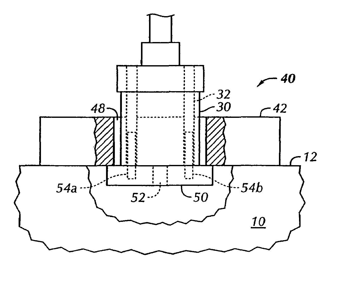
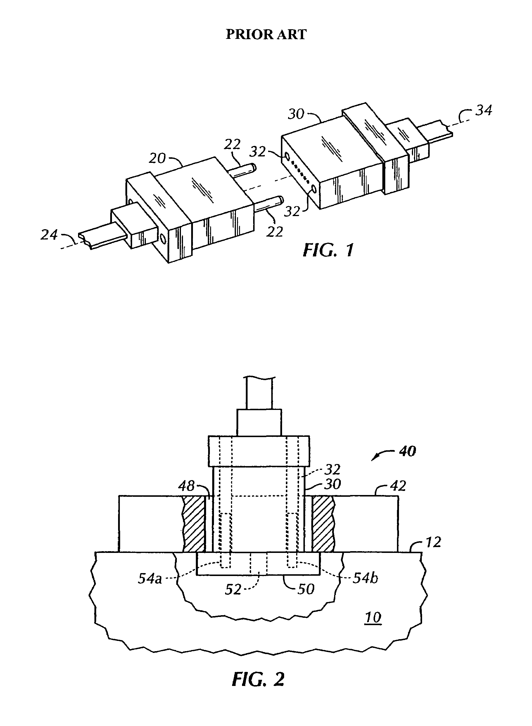
[0027]Referring to FIGS. 1–3, there is shown a first preferred embodiment of a fixture 40 in accordance with the present invention. The fixture 40 is used in combination with an interferometric microscope 10 to hold a female multi-fiber optical connector 30. As shown in FIG. 1, and as discussed above, it is known in the art to provide male and female multi-fiber optical connectors 20, 30, respectively. The male connector 20 is typically provided with a pair of guide pins 22. The female connector 30 is p...


PUM

PropertyMeasurementUnit
lengthaaaaaaaaaa
lengthaaaaaaaaaa
end face angleaaaaaaaaaa

Abstract

A holding fixture for use with an interferometric optical microscope is adapted to receive an optical fiber connector. The fixture comprises a base plate mountable to the microscope and having a base plate opening sized to receive the optical fiber connector. An aperture plate is connected to the base plate, the aperture plate having an aperture opening overlapping the base plate opening. The fixture allows the optical fiber connector to be held in a precise and repeatable orientation relative to the microscope in turn facilitating accurate and precise measurements of endface geometry of the optical fiber connector. A method of using the fixture allows a calibration factor to be calculated for the fixture.

Description

CROSS-REFERENCE TO RELATED APPLICATIONS[0001]This application claims benefit of U.S. Provisional Patent Application 60 / 396,248, “Interferometric Holding Fixture for Multifiber Optical Connectors”, filed Jul. 16, 2002.BACKGROUND OF THE INVENTION[0002]The present invention relates to a fixture and method for measuring the end face geometry and angle of polish of guide pin based multi-fiber fiber optic connectors using an interferometric microscope.[0003]Optical fibers allow the transmission of data over great distances using light signals. The basic construction of the optical fiber which is made of either glass, a polymeric material or a combination of both, includes a small core, surrounded by a lower index cladding material. The light signal travels through the core and if it travels to the edge of the core, the refractive index of the cladding causes it to reflect back toward the center and continue down the fiber core. A high performance fiber optic connection is made between two...

Claims


Application Information

Patent Timeline
Patent Type & Authority Patents(United States)
IPC IPC(8): G02B6/36G01N21/00G02B6/00G02B6/38G02B6/42
CPCG02B6/3807G02B6/385G02B6/4292G02B6/3882G02B6/3885G02B6/3863
Inventor NORLAND, ERIC
Owner THORLABS INC
Why Eureka
Try Eureka