
Connection of streamlined-section struts

a technology of streamlined section and strut, which is applied in the direction of rod connection, manufacturing tools, mechanical apparatus, etc., can solve the problems of reducing the service life of the streamlined section strut, so as to achieve the effect of reducing the weigh

Inactive Publication Date: 2006-02-28
BOSCH REXROTH AG
View PDF28 Cites 73 Cited by
  • Summary
  • Abstract
  • Description
  • Claims
  • Application Information

AI Technical Summary

Benefits of technology

[0007]On the basis of the inventive structure of the connector, the surface of the connector mounted to the second streamlined-section strut that faces toward the front face of the first streamlined-section strut connects essentially flush with the outer edge of the edge flange of the second streamlined-section strut. Thus, no parts are provided in the area of the contact surfaces for the first streamlined-section strut that would interfere with its mounting, which must be removed before the mounting of the first streamlined-section strut by cutting or sawing machining. This saves valuable machining time. Since accordingly, the previously described cutting or sawing is eliminated, with use of the connection of the present invention, the subsequent installation of streamlined-section struts in an already existing streamlined-section strut assembly is possible without further machining.
[0020]To reduce the weight, in addition, it can be provided that in the upper surface of the connector facing the first strut and / or in the upper surface of the connector facing away from the first strut, at least one further recess is provided.

Problems solved by technology

Finally, the subsequent attachment of streamlined-section struts in an existing streamlined-section strut assembly is made difficult, since an already mounted streamlined-sections strut must be sawed.
Thus, no parts are provided in the area of the contact surfaces for the first streamlined-section strut that would interfere with its mounting, which must be removed before the mounting of the first streamlined-section strut by cutting or sawing machining.
This saves valuable machining time.

Method used


Image

  • Connection of streamlined-section struts
  • Connection of streamlined-section struts
  • Connection of streamlined-section struts

Examples


Embodiment Construction

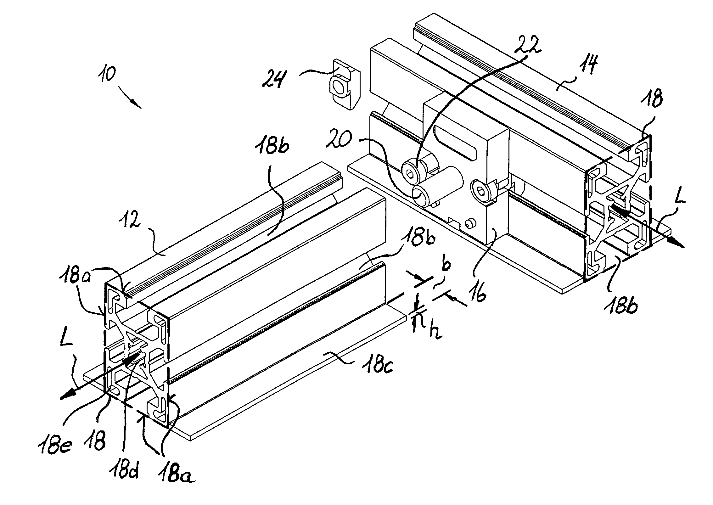
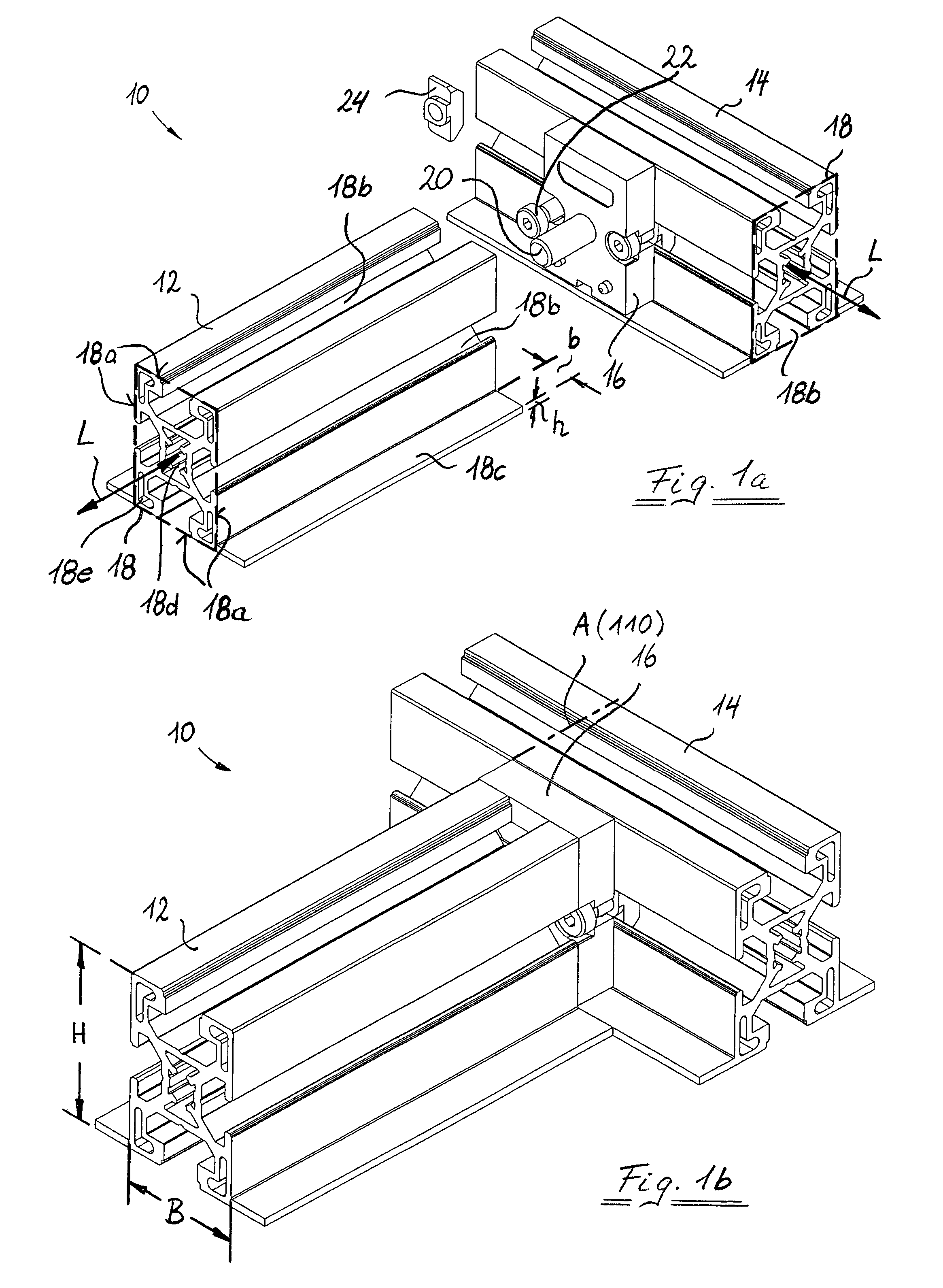
[0028]In FIGS. 1a and 1b, a T-connection 10 of a first streamlined-section strut 12 is shown with a second streamlined-section strut 14 with the use of a connector 16.

[0029]Both streamlined-section struts 12 and 14 have an identical, essentially rectangular base cross section 18 and extend in a longitudinal strut direction L. In each of the four lateral surfaces 18a of the streamlined-section struts 12, 14, a T-shaped mounting groove 18b is provided, that is a groove that opens toward a respective lateral surface 18a and is undercut on both sides of the opening. In addition, an edge flange 18c of a predetermined width b and a predetermined height h is provided each on two opposite lateral surfaces 18a at the edge. The height of the streamlined-section struts 12, 14 has the value H, and the width of the base cross section 18 has the value B, according to FIG. 1b.

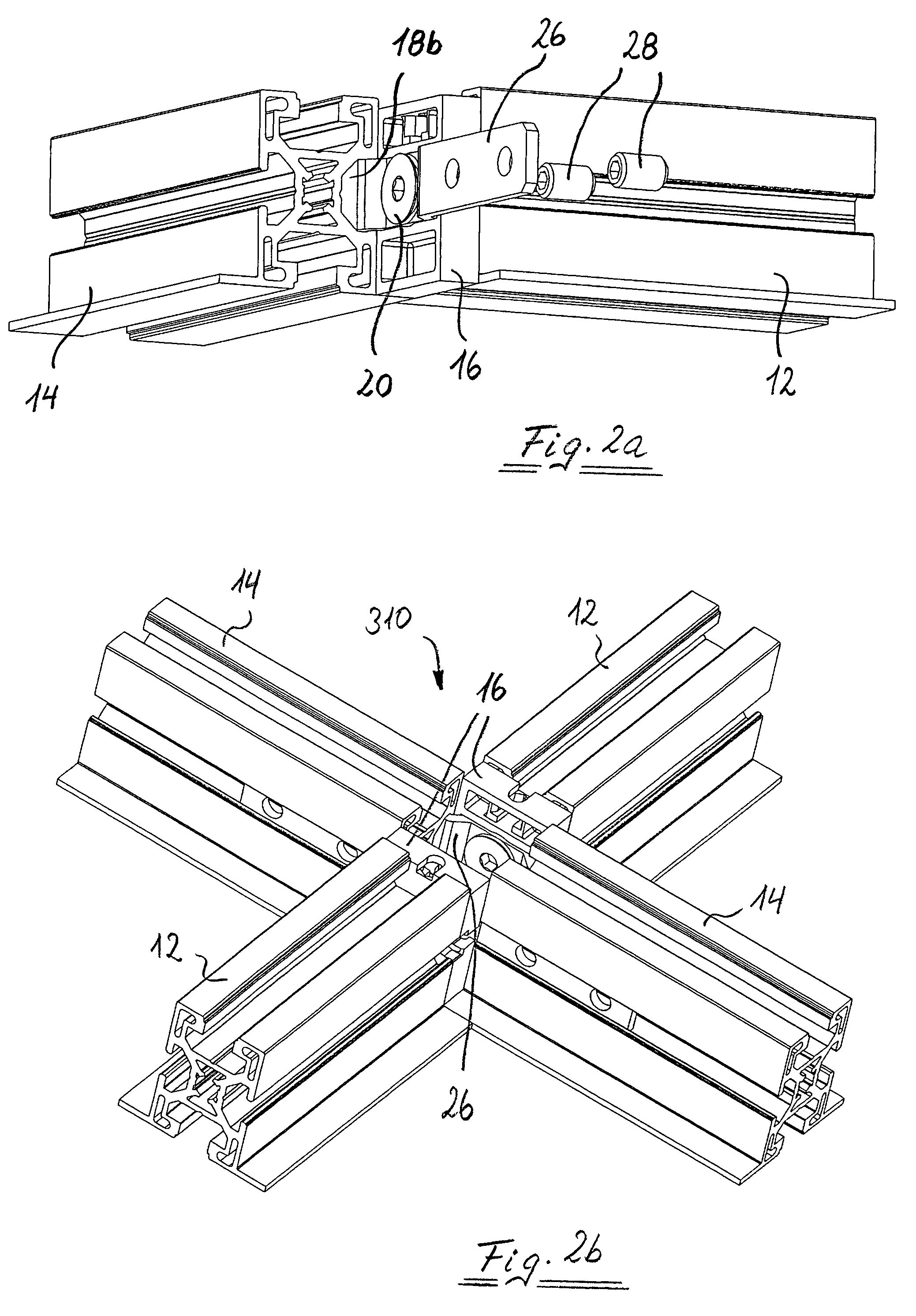
[0030]As can be seen in FIG. 3b, the connector 16 is generally quadrilateral-shaped with a height X, a width Y, and a dept...


PUM


Abstract

A connection (10) of two streamlined-section struts (12, 14) running orthogonally to one another with an essentially rectangular base cross section (18) uses a connector (16). The lateral surface (18a) of one (14) of the streamlined-section struts has a mounting groove (18b), as well as an edge flange (18c), which projects substantially orthogonally from an edge of this lateral surface (18a) at a predetermined distance (b). The connector (16) can be attached to the lateral surface (18a) of the one streamlined-section strut having the mounting groove (18b) and to the front side of the other streamlined-section strut (12). The contour of the connector (16)is accommodated substantially completely within the base cross section (18) of the other streamlined-section strut (12). In addition, the depth of the connector (16) is essentially the same as the predetermined distance (b).

Description

BACKGROUND OF THE INVENTION[0001]The present invention relates to a connection of two streamlined-section struts running substantially orthogonally to one another with a substantially rectangular base cross section, whereby at least one of these streamlined-section struts has an edge flange, which projects from the edge of one of the lateral surfaces substantially orthogonally.[0002]These types of connections of streamlined-section struts are used for assembly of ceilings, for example. In this connection, DE 86 24 567 U1 discloses the use of a connector for connecting streamlined-section struts with identical, essentially rectangular base cross sections, whose contour, likewise, is identical to the base cross section. Although in this document, streamlined-section struts with edge flanges are not mentioned and it can be concluded that the connection described in this document is not contemplated for streamlined-section struts, it should be noted that this connection for streamlined-...

Claims


Application Information

Patent Timeline
IPC IPC(8): F16B9/00E04B9/14F16B7/18
CPCE04B9/14F16B7/187Y10T403/4677Y10T403/4662Y10T403/4681Y10T403/3906Y10T403/39Y10T403/4665Y10T403/4671Y10T403/4602F16B2200/20F16B2200/30F16B2200/40F16B2200/205F16B2200/403
Inventor LUDWIG, PETERKAISER, UWEHENNEBERG, JENS
Owner BOSCH REXROTH AG
Learn More