Flexible universal joint sub connection for down hole mud motor method and apparatus

a universal joint and motor technology, applied in mechanical equipment, drilling pipes, couplings, etc., can solve the problems of inability to easily adapt to conventional sealing arrangements, unacceptable adverse effects on the operation life of the drive shaft, and high abrasion of drilling fluids, etc., to achieve convenient replacement, improve wear resistance, and reduce the effect of cos

Active Publication Date: 2006-02-28
NAT OILWELL VARCO LP
View PDF11 Cites 32 Cited by
  • Summary
  • Abstract
  • Description
  • Claims
  • Application Information

AI Technical Summary

Benefits of technology

[0005]What is really required is a more dependable and rugged drive shaft universal joint assembly, which is virtually unaffected by the harsh environment for a considerable time but which can be replaced quickly and easily at a nominal cost.
[0006]According to the invention there is provided a mud motor universal joint assembly that includes a pair of adjacent cylindrical joints having threaded connection means at one end of each joint. Each joint has interlocking jaws at the other end, each joint having an internal blind tapered bore within the interlocking jaw portion containing a hardened cylindrical load-bearing member. A hardened cylindrical rod member, inserted into the internal tapered bore of each joint and retained therein by perpendicular retaining pins, connects the two interlocking joints. The joints, connecting rod, and bearing members are surface hardened to improve wear. No balls or seals are required and the internal hardened connecting rod and bearing members are easily replaced, if necessary, at a nominal cost.

Problems solved by technology

It is generally believed that the drive shaft universal joint assembly cannot tolerate abrasive drilling fluids, thereby having an unacceptable adverse effect on the operational life of the drive shafts.
However, these universal joint assemblies do not readily lend themselves to conventional sealing arrangements.
Universal joint wear in this instance is generally associated with pitting of the various ball surfaces that characterize these types of universal joint arrangements resulting from the high abrasiveness of the drilling fluids.

Method used


Image

  • Flexible universal joint sub connection for down hole mud motor method and apparatus
  • Flexible universal joint sub connection for down hole mud motor method and apparatus
  • Flexible universal joint sub connection for down hole mud motor method and apparatus

Examples


Embodiment Construction

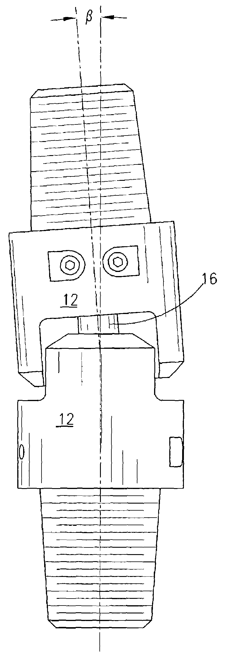
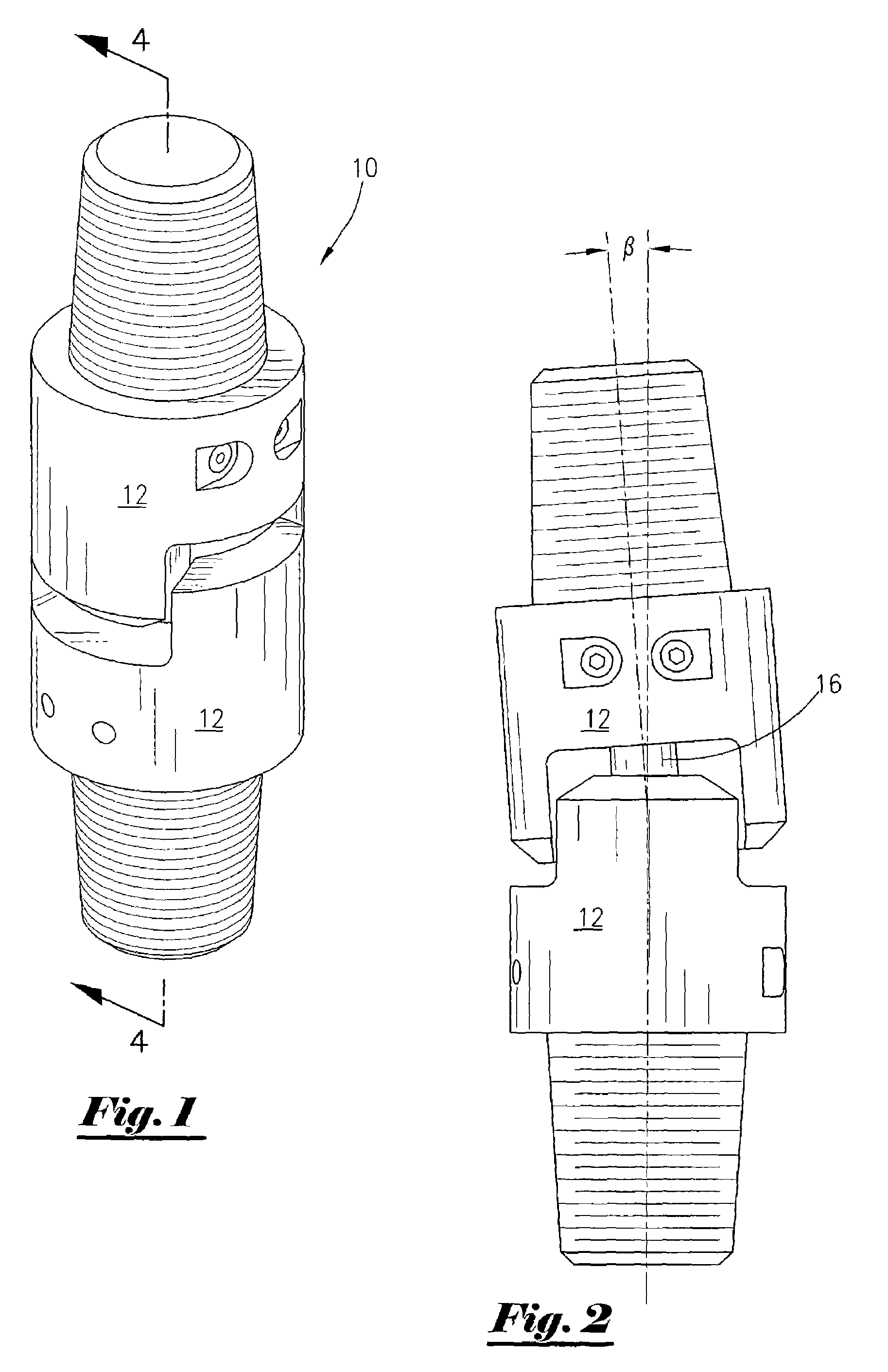
[0014]As shown in FIG. 1 the disclosed universal joint assembly 10 includes a pair of interfacing joint member assemblies 12. Joint member assemblies 12, are loosely retained one to the other by the connecting rod 16 as shown in FIG. 2. This loose fitting arrangement allows torque to be transmitted from one member to the other via interfacing jaw portion while still allowing for angular defection “β”. Unlike universal joints generally used in connection with mud motor drives, the joint assembly 10 does not rely on the connecting rod 16 to transmit torque. The connecting rod 16 simply retains the joint member assemblies 12 in close proximity with each other longitudinally. Obviously, angulations of the drive shaft may be increased by adding a second joint assembly connected by an intermediate tubular member thereby compounding the deflection angle “β” relative to the central axes of the joint assembly 10.

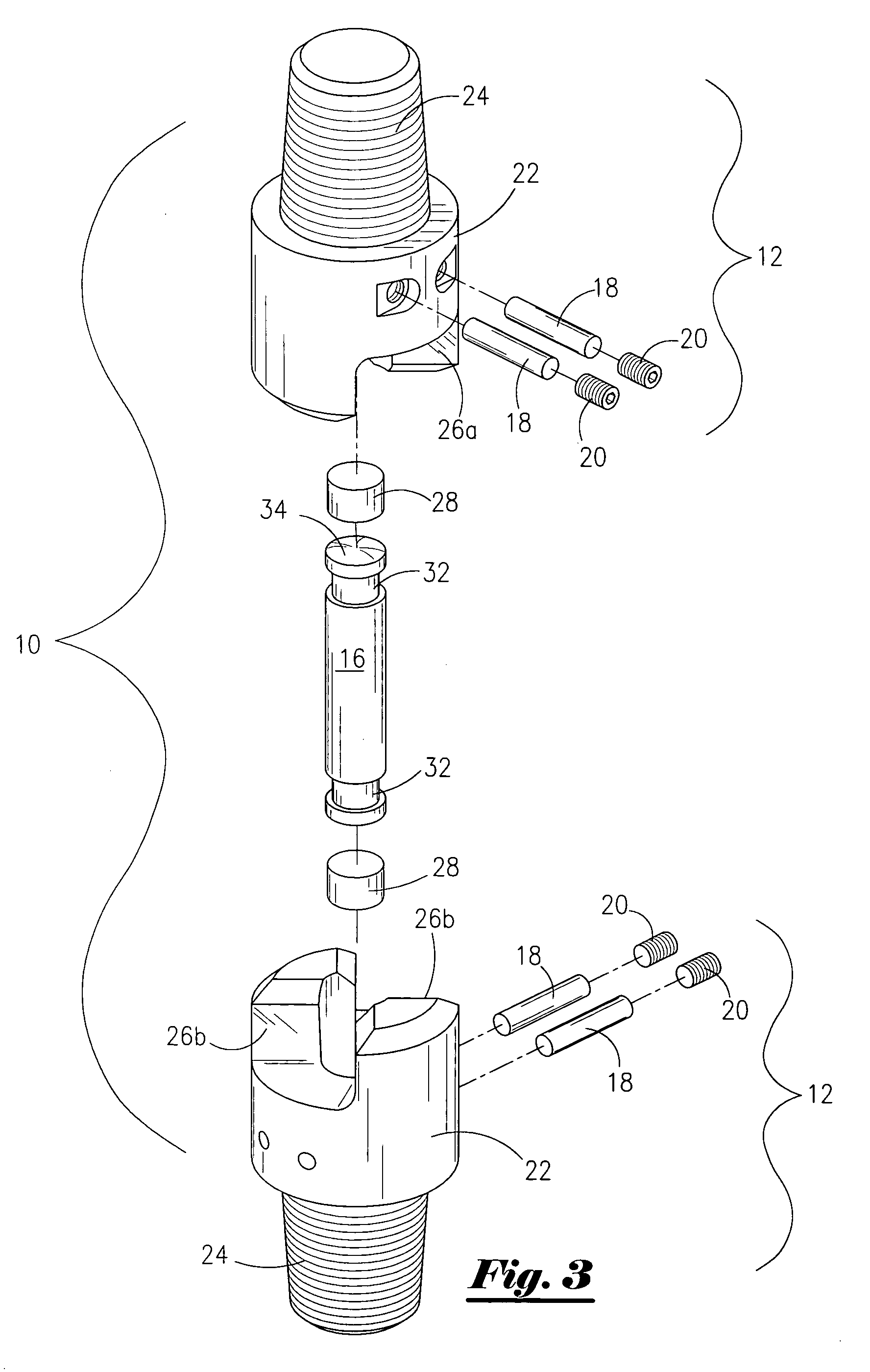
[0015]The joint member assemblies 12 as seen in the exploded view, FIG. 3, furth...


PUM


Abstract

A mud motor universal joint assembly that includes a pair of adjacent cylindrical joints having threaded connection means at one end and interlocking jaws at the other, each cylindrical joint having an internal blind tapered bore within the interlocking jaw portion containing a hard cylindrical load bearing member. The two joints are connected by a hardened cylindrical rod member inserted into the internal blind tapered bore of each joint and retained therein by perpendicular retaining pins. The joints, connecting rod, and bearing members are surface hardened to improve wear. No balls or seals are required and the internal hardened connecting rod and bearing members are easily replaced if necessary at a nominal cost.

Description

FIELD OF THE INVENTION[0001]This invention relates generally to universal joints and more particularly to universal joints used in down hole mud motors.GENERAL BACKGROUND[0002]Down hole mud motors are used within the oil industry for earth boring operations. These mud motors rotate eccentrically. The eccentric rotation must be converted into concentric rotation in order for the drill bit to function correctly. The current state of the art generally accomplishes this conversion by providing a drive shaft having some type of universal joint connection that connects the down hole motor to a drive assembly rotating the drill bit.[0003]It is generally believed that the drive shaft universal joint assembly cannot tolerate abrasive drilling fluids, thereby having an unacceptable adverse effect on the operational life of the drive shafts. Attempts have been made to effectively seal the universal joint assemblies so as to prolong their operational life. However, these universal joint assembl...

Claims


Application Information

Patent Timeline
Patent Type & Authority Patents(United States)
IPC IPC(8): F16D3/18
CPCF16D3/72F16D3/18E21B17/03
Inventor KERSTETTER, SCOTT
Owner NAT OILWELL VARCO LP
Why Eureka
Try Eureka